background image

85

MS 311, MS 391

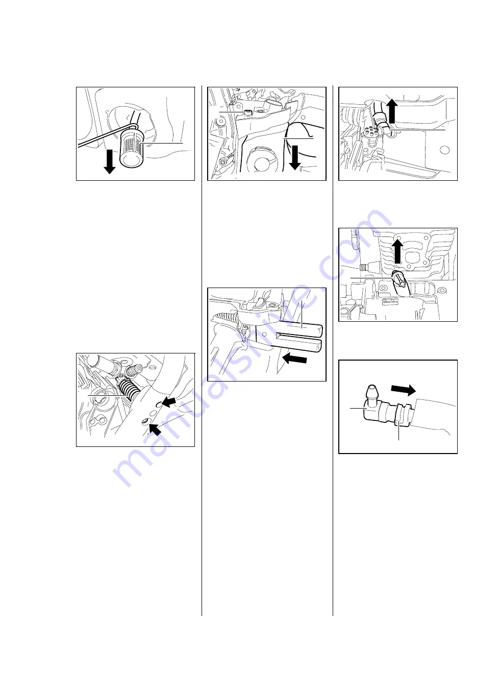
– Open the tank cap.

:

Use hook 5910 893 8800 to 
remove the pickup body (1) from 
the fuel tank.

Do not overstretch the fuel hose.

:

Pull off the pickup body (1).

– Reassemble in the reverse 

sequence.

12.11.2 Fuel Hose

:

Take out the screws (arrows) and 
pry the AV spring (1) out of the 
handlebar.

1

0001RA410 TG

4903RA243 TG

1

– Remove the shroud

b

6.4

– Remove the air guide shroud, 

b

12.4

:

Take out the screw (1).

:

Lower the tank housing (2).

:

Slide the wooden assembly 
block (1) between the engine 
housing and tank housing.

4903RA060 TG

1

2

4903RA108 TG

1

:

Pull out the fuel hose (1) with 
connector.

:

Remove the fuel hose (1).

:

Pull the fuel hose (2) off the 
connector (1).

4903RA164 TG

1

4903RA000 TG

1

0001RA412 TG

1

2

Summary of Contents for MS 311

Page 1: ...STIH STIHL MS 311 391 2009 06 ...

Page 2: ...Piston Rings 38 6 9 Decompression Valve 38 7 Ignition System 39 7 1 Ignition Timing 39 7 2 Preseparator 39 7 3 Ignition Module 39 7 4 Testing the Ignition Module 41 7 5 Spark Plug Boot Ignition Lead 42 7 6 Flywheel 43 7 7 Short Circuit Wire 44 7 7 1 Testing 44 7 7 2 Removing and Installing 44 7 7 3 Ground Wire 46 7 7 4 Contact Spring 46 7 8 Ignition System Troubleshooting 48 8 Rewind Starter 51 8 ...

Page 3: ...phragm 74 12 6 4 Air Valve 76 12 6 5 Levers on Throttle Shaft 76 12 6 6 Adjusting Screws 77 12 7 Carburetor Adjustment 79 12 7 1 Basic Setting 79 12 7 2 Standard Setting 80 12 8 Carburetor Carrier 81 12 9 Intake Manifold 82 12 10 Tank Vent 83 12 10 1 Testing 83 12 10 2 Removing and Installing 84 12 11 Fuel Intake 84 12 11 1 Pickup Body 84 12 11 2 Fuel Hose 85 12 11 3 Fuel Suction Hose 86 12 11 4 T...

Page 4: ...ual Use the part numbers to identify the tools in the STIHL Special Tools manual The manual lists all special servicing tools currently available from STIHL Symbols are included in the text and pictures for greater clarity The meanings are as follows In the descriptions N Action to be taken as shown in the illustration above the text Action to be taken that is not shown in the illustration above t...

Page 5: ...fuel All work with fuel must be performed outdoors only Spilled fuel must be wiped away immediately Always perform leakage test after working on the fuel system and the engine Always replace damaged parts Check disassembled parts for wear or damage before re installing replace as necessary Run the machine only with the shroud mounted in position there is otherwise a risk of injury from the fanwhee...

Page 6: ...pm Engine housing leakage test at gauge pressure 0 5 bar under vacuum 0 5 bar 2 2 Fuel System Carburetor leakage test at gauge pressure 0 8 bar Operation of tank vent at gauge pressure 0 5 bar Fuel as specified in instruction manual 2 3 Ignition System Air gap between ignition module and fanwheel 0 20 0 30 mm Spark plug resistor type NGK BPMR 7 A BOSCH WSR6F Electrode gap 0 5 mm 2 4 Chain Lubricat...

Page 7: ...ndlebar plug AV spring 3 0 Screw P 6x26 5 Handlebar tank housing right polymer 7 0 Screw P 6x26 5 Handlebar tank housing bottom polymer 7 0 Screw P 6x25 Hand guard fan housing 8 0 Screw M 6x30 Shroud engine housing 10 0 Screw P 6x38 Chain catcher bearing plug 6 0 Screw P 5x16 Spiked bumper engine housing 4 0 Screw M 4x12 Manifold cylinder 4 0 3 Screw P 6x21 5 Bearing plug engine housing 6 0 Screw ...

Page 8: ... the hole and rotate it counterclockwise until it drops down slightly Tighten the screw clockwise to the specified torque Coat micro encapsulated screws with medium strength threadlocking adhesive before re installing This procedure ensures that the screw engages properly in the existing thread and does not form a new thread and weaken the assembly Power screwdriver setting for polymer DG and P sc...

Page 9: ...h Readjust with idle speed screw LA counterclockwise Clutch springs stretched or fatigued Replace the clutch springs or install new clutch Clutch spring hooks broken Replace the clutch springs or install new clutch Loud noises Clutch springs stretched or fatigued Replace the clutch springs or install new clutch Needle cage damaged Fit new needle cage Clutch shoe retainer broken Install new retaine...

Page 10: ...ll new clutch Clutch drum badly worn Install new clutch drum Brake band blocked Check freedom of movement and operation of brake band Saw chain rotates at idle speed Engine idle speed too high Readjust with idle speed screw LA counterclockwise Clutch springs stretched or fatigued Replace the clutch springs or install new clutch Clutch spring hooks broken Replace the clutch springs Saw chain does n...

Page 11: ...ake hose and pickup body Valve in oil tank blocked Clean or replace valve Teeth on worm worn Install new worm Worm drive spring broken Install new worm Oil pump damaged or worn Install new oil pump Machine losing chain oil Oil pump body damaged Install new oil pump Oil pump damaged or worn Install new oil pump Oil intake hose connection damaged Install new oil intake hose Oil pump delivers insuffi...

Page 12: ...rter rope can be pulled out almost without resistance crankshaft does not turn Guide peg on pawl or pawl itself is worn Fit new pawl Spring clip on pawl fatigued Fit new spring clip Starter rope is difficult to pull or rewinds very slowly Starter mechanism is very dirty Thoroughly clean complete starter mechanism Lubricating oil on rewind spring becomes viscous at very low outside temperatures spr...

Page 13: ...ch oil Use correct mixture of fuel and oil Incorrect air gap between ignition module and flywheel Set air gap correctly Flywheel cracked or damaged or pole shoes have turned blue Install new flywheel Ignition timing out of adjustment flywheel warped machined key in flywheel sheared Install new flywheel check crankshaft stub for damage and replace crankshaft if necessary Weak magnetization in flywh...

Page 14: ...isc on diaphragm is deformed and presses constantly against the inlet control lever Fit a new metering diaphragm Metered diaphragm deformed Fit a new metering diaphragm Poor acceleration Setting of low speed screw too lean Check basic carburetor setting correct if necessary Setting of high speed screw too lean Check basic carburetor setting correct if necessary Inlet needle sticking to valve seat ...

Page 15: ...le jet bores or ports blocked Clean the carburetor Low speed screw too rich or too lean Reset low speed screw L correctly Setting of idle speed screw LA incorrect throttle shutter completely closed Reset idle speed screw LA correctly Tank vent faulty Replace tank vent Leak on fuel hose from tank to carburetor Seal connections or install new fuel hose Saw chain rotates at idle speed Engine idle spe...

Page 16: ...res or ports blocked Clean the carburetor Pump diaphragm damaged or fatigued Fit new pump diaphragm Ignition timing wrong flywheel out of adjustment key in flywheel has sheared off Fit key if necessary and secure flywheel properly or install new flywheel Engine running extremely rich has no power and a very low maximum speed Air valve does not open Check the carburetor and service or replace if ne...

Page 17: ...ot deliver full power or runs erratically Piston rings worn or broken Fit new piston rings Muffler spark arresting screen carbonized Clean the muffler inlet and exhaust replace spark arresting screen replace muffler if necessary Air filter dirty Replace air filter Fuel impulse hose severely kinked or damaged Fit new hoses or position them free from kinks Decompression valve is not closed Close che...

Page 18: ...cylinder wall arrow as shown Apply wrench to hexagon arrow and unscrew the clutch 1 Note that the clutch has a left hand thread Disassembling Use hook 2 5910 890 2800 to remove the clutch springs 1 4903RA106 TG 1 1 4903RA003 TG 4903RA004 TG 2 1 Pull the clutch shoes off the carrier Remove the retainers 1 Clean all parts b 14 Replace any damaged parts If the clutch is noticeably worn replace all th...

Page 19: ...ing 1 to the clutch shoes Use the hook 2 5910 890 2800 to attach the other ends of the springs and press them firmly into the clutch shoes Check the clutch all springs arrows must be properly attached 4903RA010 TG 1 2 4903RA011 TG Make sure the washer 1 is in place Installed position is correct when TOP arrow faces outwards Position the clutch on the crankshaft stub so that the raised hexagon arro...

Page 20: ...ll the clutch drum see instruction manual Pull off the needle cage 1 Clean the needle cage and crankshaft stub b 14 Lubricate the needle cage and crankshaft stub b 14 Inspect the clutch drum 1 for signs of wear If there are signs of serious wear on the inside diameter of the clutch drum 1 check the remaining wall thickness If it is less than about 80 of the original thickness install a new clutch ...

Page 21: ... a brief period max 3 seconds the chain must not rotate With the chain brake released open the throttle wide and activate the brake manually the chain must come to an abrupt stop The braking time is in order if deceleration of the saw chain less than a second is imperceptible to the eye If the chain brake does not operate properly refer to troubleshooting b 3 2 5 2 Brake Band Remove the clutch dru...

Page 22: ... brake lever 2 and then swing it in the direction of its seat 4903RA020 TG 2 1 219RA049 TG 4903RA021 TG 2 1 Position the brake band 1 it the guide arrow first Disengage the chain brake Push the brake band 1 over the guide lugs arrows and into its seat Push the brake band 1 into its seat arrow as far as stop 4903RA022 TG 4903RA023 TG 1 4903RA024 TG 1 Fit the screw 1 on the underside of the machine ...

Page 23: ... disconnect the brake spring 1 from the anchor pin arrow Remove the brake spring from the brake lever Remove the shroud b 6 4 Take out the screws arrows Remove the sleeve 1 Lift the hand guard a little and remove the fan housing 4903RA027 TG 1 4903RA119 TG Remove the E clip 1 Lift and turn the strap 1 slightly push it towards the hole arrow and remove it Remove the spacer sleeve 2 from the brake l...

Page 24: ...p the holes 4903RA032 TG 1 2 4903RA033 TG 1 Push the hand guard with brake lever 1 over the machine until they are positioned against the pivot pins arrows Lift the bearing boss of the hand guard and the brake lever a little and position them over the pivot pins arrows Turn the cam lever 1 to one side until the cam of the hand guard arrow slips passed it Push the hand guard bearing boss and the br...

Page 25: ...2 3 Check the cam lever 1 and spring 2 and replace if necessary Check the condition of the cam contour arrow and replace the hand guard if necessary Installing Position the cam lever 1 so that its cam arrow faces the pin 3 Push the cam lever 1 on to the pivot pin 2 4903RA040 TG 2 1 4903RA041 TG 1 2 3 Fit the E clip 1 Attach the spring 1 to the cam lever so that the open side of the spring hook arr...

Page 26: ...at the knurling on the pin meshes with the existing knurling in the bore 4903RA044 TG 1 3 5 2 4 4903RA045 TG Turn pin back and forth as necessary Drive home the pins 1 and 2 as shown in the illustrations Pin 1 a about 2 9 3 3 mm Pin 2 b about 4 3 4 7 mm Drive home pins 3 4 and 5 as specified below 4903RA046 TG 1 2 b a 1 24903RA047 TG 4903RA048 TG 3 5 4 Pin 3 a about 11 6 11 8 mm Pin 4 b about 4 6 ...

Page 27: ... 14 Reassemble in the reverse sequence 4903RA052 TG 1 2 4 2 1 3 2 533RA058 TG 5 7 Bar Mounting Studs Push stud puller 5910 893 0501 1 over the collar studs 2 as far as it will go and unscrew the studs counterclockwise Before installing coat threads 1 and 2 of collar studs with threadlocking adhesive b 14 Fit the collar studs and tighten them down firmly Reassemble all other parts in the reverse se...

Page 28: ... 4903RA057 TG 2 1 1 Remove the exhaust gasket 1 Remove and install the spark arresting screen see instruction manual Installing Hold the machine upright Inspect and clean the sealing faces arrows and remove any gasket residue Always replace components with damaged sealing faces 0001RA076 TG 1 0001RA079 TG Position the exhaust gasket 1 so that the warts arrows point towards the cylinder Fit the exh...

Page 29: ... pump 0000 850 1300 6 2 1 Preparations Remove the shroud b 6 4 Pull off the boot and unscrew the spark plug Set the piston to top dead center This can be checked through the spark plug hole Remove the decompression valve b 6 9 Fit the plug 1 1122 025 2200 and tighten it down firmly Fit the spark plug 2 and tighten it down firmly 0001RA083 TG 1 2 Pry out the plugs Do not refit old plugs always fit ...

Page 30: ...ion However if the pressure continues to rise reduced vacuum in the engine the oil seals must be replaced b 6 3 After finishing the test push the ring to the right to vent the pump Continue with pressure test b 6 2 3 6 2 3 Pressure Test Carry out the same preparations as for the vacuum test b 6 2 2 4903RA238 TG 3 2 4 1 Push ring 1 to the right Operate the lever 2 until the pressure gauge 3 indicat...

Page 31: ...aws 0000 893 3706 Clamp the puller arms Pull out the oil seal Take care not to damage the crankshaft stub Clean the sealing face b 14 Lubricate sealing lips of new oil seal with grease b 14 Installing Slip the oil seal open side snap ring facing outwards over the crankshaft stub Use press sleeve 2 1122 893 2405 to install the oil seal 1 The seating face must be flat and free from burrs Wait about ...

Page 32: ...ng sleeve 1 1122 893 4600 Slip the oil seal open side snap ring facing outwards over the installing sleeve Remove the installing sleeve 1 Use press sleeve 1 1122 893 2405 to install the oil seal 2 The seating face must be flat and free from burrs 1 4903RA065 TG 4903RA276 TG 2 1 Fit the E clip 1 Wait about one minute then rotate the crankshaft several times Reassemble all other parts in the reverse...

Page 33: ...e carburetor b 12 5 Remove the manifold b 12 9 Remove the muffler b 6 1 Remove the decompression valve b 6 9 Remove AV spring from handlebar b 9 4 Take out the screws arrows 4903RA072 TG Use the lug arrow to pry the cylinder 1 upwards Remove the cylinder with crankshaft Pull the crankshaft 1 out of the bearing seats arrows Carefully pull the crankshaft 1 with piston out of the cylinder Check the c...

Page 34: ...s must be in perfect condition Always replace components with damaged sealing faces Installing Use oil seal 1 9638 003 1581 for replacement on closed engine Use oil seal 2 9639 003 1585 for replacement on opened engine 4903RA081 TG 2 1 4903RA275 TG Fit the installing sleeve 1 1118 893 4602 Push the new oil seals open side facing inwards on to the crankshaft stubs Fit the E clip 1 1 533RA107 TG 1 5...

Page 35: ...rings are compressed by the cylinder s taper Carefully push the piston with crankshaft 1 into the cylinder Place the crankshaft with bearings and oil seals in the bearing seats making sure the oil seals are firmly against their stops arrows in the cylinder 4903RA076 TG 1 4903RA090 TG Inspect and clean the sealing face on the engine housing and remove any gasket residue b 14 The sealing faces must ...

Page 36: ...ring form an inseparable unit When fitting a replacement crankshaft always install new ball bearings and oil seals Before installing clean the crankshaft b 14 Heated ball bearings must be installed quickly because the crankshaft stubs absorb heat and expand 1 4903RA083 TG 4903RA084 TG 2 1 Heat the bearing inner race to about 150 C 300 F Push the ball bearing onto the straight crankshaft stub as fa...

Page 37: ... the connecting rod Remove the piston Inspect the piston rings and replace if necessary b 6 8 Pull out the needle cage 1 check it and replace if necessary b 14 Installing Lubricate the needle cage with oil and push it into the connecting rod Position the piston as shown so that the mark arrow points to the rear and the long crankshaft stub 1 is on the right Place the piston on the connecting rod 1...

Page 38: ...til the magnet butts against the end of the guide slot Use a suitable base Remove the sleeve and slip it onto the other end of the shank the inner pin must point towards the flat face 0001RA483 TG 216RA178 TG Apply the installing tool 5910 890 2212 with the sleeve s taper against the piston boss hold the piston steady center the tool shank exactly and press home until the snap ring slips into the ...

Page 39: ... arrows Position the piston rings so that the radii at the ring gap meet at the fixing pin in the piston groove arrows Check correct installed position of the piston rings arrows Install the piston b 6 7 Reassemble all other parts in the reverse sequence 533RA136 TG 533RA137 TG 6 9 Decompression Valve Remove the shroud b 6 4 Unscrew the decompression valve 1 Check the sealing cone arrow on the dec...

Page 40: ... 8 2 Take out the screw 1 Remove the preseparator 2 Reassemble in the reverse sequence 7 3 Ignition Module The ignition module accommodates all the components required to control ignition timing There are two electrical connections on the coil body High voltage output 1 with ignition lead The connector tag 2 for the short circuit wire 2 1 4903RA254 TG 4903RA092 TG 2 1 Testing in the workshop is li...

Page 41: ...tting gauge 1 1111 890 6400 between the arms of the ignition module and the flywheel magnet The setting gauge is not shown in the illustration Push the ignition module 1 back and hold it there the flywheel must move freely Rotate the flywheel until the magnet poles arrows are next to the ignition module 1 Press the ignition module 1 against the setting gauge Hold the ground wire terminal steady it...

Page 42: ...wn firmly Connect the spark plug boot to the input terminal 1 and push the tester s output terminal 3 onto the spark plug High voltage risk of electric shock Crank the engine quickly with the rewind starter and check spark in the tester s window 2 The engine may start and accelerate during the test If a spark is visible the ignition system is in order If no spark is visible in the window 2 check t...

Page 43: ... 8 165RA185 TG 1 2 3 4 5 7 5 Spark Plug Boot Ignition Lead The ignition module 1 and ignition lead 2 form a unit A new ignition module must be installed if the ignition lead is damaged Remove the shroud b 6 4 Use suitable pliers to pull the leg spring out of the spark plug boot Unhook the leg spring from the ignition lead Pull the boot off the ignition lead Remove the sleeve 4903RA227 TG Installin...

Page 44: ... the screws 1 as far as stop Tighten the screws uniformly Screw home the thrust bolt 2 clockwise until the flywheel is released from the crankshaft Remove the puller 3 1135 890 4500 from the flywheel The flywheel and magnet poles arrows must not be damaged or have turned blue Replace flywheel if necessary The flywheel and crankshaft stub must be free from grease before assembly 0001RA165 TG 1 1 2 ...

Page 45: ...the ignition system with the aid of the troubleshooting chart b 7 8 Reassemble in the reverse sequence 1 2 4903RA263 TG 7 7 2 Removing and Installing Pull the boot off the spark plug Remove the shroud b 6 4 Remove the fan housing b 8 2 Disconnect the choke rod b 10 2 1 Remove the contact spring b 7 7 4 The ground and short circuit wires are combined in a wiring harness Pull the ignition lead 3 out...

Page 46: ... wire 1 into the guides arrows Install the filter base b 12 3 Position the ring terminal 1 so that its crimped side faces up Push the ring terminal 1 onto the pin arrow as far as stop Push the short circuit wire 1 into the guides arrows 4903RA103 TG 1 4903RA107 TG 1 4903RA261 TG 1 Position the short circuit wire so that it forms a loop and can move along with the switch shaft Check that short circ...

Page 47: ...short circuit wire in a wiring harness If damaged the wiring harness must be replaced Check for contact and continuity and replace the wiring harness b 7 7 7 7 4 Contact Spring Remove the shroud b 6 4 Remove the choke rod b 10 2 1 Move the switch shaft 1 towards the tank housing until the contact spring 2 is free 4903RA113 TG 2 1 Lift the contact spring 1 over the lug arrow and pull it out Check t...

Page 48: ...ing in position Lift the contact spring 1 and push it over the switch shaft Check operation short circuit wire s connector must touch the contact spring arrow in position 0 Reassemble all other parts in the reverse sequence 4903RA116 TG 4903RA117 TG 1 4903RA118 TG ...

Page 49: ...d Electrode gap correct Contacts shorted Clean readjust or replace the plug b 7 4 Check the spark plug boot Firmly seated on plug leg spring Leg spring hook in center of ignition lead Boot damaged If necessary install new spark plug boot and or leg spring b 7 5 Test ignition system with ZAT 3 or ZAT 4 use ZAT 3 as main spark gap see TI 32 94 b 7 4 1 ...

Page 50: ...ing Spark plug boot Holes cracks Resistance spark plug boot to ground spec 1 5 12 kΩ Check resistance of ignition lead spark plug boot and ignition module removed Spec 10 Ω If necessary install new spark plug boot and or ignition lead with module b 7 3 Check short circuit wire Wire damaged Connectors firmly seated Check continuity replace wiring harness if necessary b 7 7 2 1 3 yes no 2 Powerful s...

Page 51: ... or carburetor Check engine for leaks Check position of flywheel on crankshaft b 7 6 b 6 5 yes Check operation of switch shaft Short circuit wire chafed Function between contact spring and switch shaft contact Position F no connection Position 0 connection Install new short circuit wire if necessary b 7 7 2 2 3 Powerful spark Engine runs ...

Page 52: ...re installing lubricate the rewind spring and starter post with STIHL special lubricant b 14 If clogged with dirt or pitch the entire starter mechanism including the rewind spring must be removed and disassembled Take particular care when removing the spring Clean all components b 14 8 2 Fan housing Remove the shroud b 6 4 Take out the screws arrows Lift the hand guard a little and remove the fan ...

Page 53: ...e direction of spring loops the pawls move outwards Reassemble all other parts in the reverse sequence 8 4 Rope Rotor Relieving tension of rewind spring The system will not be under tension if either the starter rope or rewind spring is broken Remove the fan housing and the segment b 8 2 Pull out the starter rope 1 about 5 cm and hold the rope rotor 2 steady 4903RA126 TG 1 2 4903RA127 TG Take thre...

Page 54: ...an housing and the segment b 8 2 Relieve tension of rewind spring b 8 4 The system will not be under tension if the starter rope is broken Remove remaining rope from the rope rotor and starter grip Do not shorten the starter rope Push the end of the starter rope 1 out a little and undo the knot Pull the starter rope out of the rope rotor and fan housing Pull the old rope out of the starter grip 49...

Page 55: ...quence 8 6 Tensioning the Rewind Spring Remove the fan housing and the segment b 8 2 Pull out a short length of starter rope 1 Use the starter rope 1 to rotate the rope rotor 2 six turns clockwise The rewind spring is now tensioned Hold the rope rotor steady since it will otherwise spin back and may damage the rewind spring 4903RA136 TG 1 2 Hold the rope rotor 2 steady Pull out the twisted rope 1 ...

Page 56: ...es ready for installation Wear a face shield and work gloves to protect your eyes and hands from injury Remove the fan housing and the segment b 8 2 Relieve tension of rewind spring if necessary and remove the rope rotor b 8 4 Remove any remaining pieces of old spring If the rewind spring can no longer be properly tensioned install a new spring Even a worn rewind spring is still pre loaded in the ...

Page 57: ... spring 1 in its original position Fit the anchor loop in its seat arrow in the fan housing 4903RA141 TG 1 4903RA142 TG 1 Fit the rewind spring 1 clockwise in the housing Hold the spring windings so that they cannot pop out Make sure that the rewind spring 1 is properly seated If necessary use suitable tools to push the rewind spring fully into its seat in the fan housing Secure the spring so that...

Page 58: ... properly on the buffer Reassemble all other parts in the reverse sequence 9 2 AV Spring on Oil Tank The antivibration spring is at the forward end of the oil tank and is secured to the underside of the machine Remove the handlebar b 9 7 Unscrew the AV spring 1 Unscrew the bearing plug 2 Screw home the bearing plug 1 as far as stop Screw the AV spring 2 into the handlebar arrow as far as stop 2 1 ...

Page 59: ...e all other parts in the reverse sequence 9 4 AV Spring on Front Handle The AV spring is located between the handle frame and cylinder Remove the shroud b 6 4 Take out the screws 1 and arrows Remove the complete AV spring 2 4903RA145 TG 1 4903RA146 TG 2 1 Installing Push the complete AV spring 1 into the handlebar Insert the screws arrows and tighten them down firmly Coat the screw 2 with threadlo...

Page 60: ...operly seated Reassemble all other parts in the reverse sequence 9 6 Annular Buffer at Ignition Side Remove the ignition module b 7 3 Pry out the annular buffer 1 Installing Line up the annular buffer 1 with its tapered end facing the engine housing Use STIHL press fluid to simplify assembly b 14 4903RA151 TG 1 4903RA152 TG 1 2 Push home the annular buffer 1 so that its bore engages the peg 2 in t...

Page 61: ...e lower guide Remove the handlebar 1 Check the annular buffer and replace it if necessary b 9 1 Installing Push the handlebar buffer 1 first into the engine housing 4903RA155 TG 1 4903RA269 TG 1 0001RA233 TG 1 Push the AV spring 1 into its seat 2 Position the handlebar 1 against the guide arrow Ease the handlebar 1 sideways and place it in the guide arrow Insert the screws and tighten them down fi...

Page 62: ...til it snaps into position Install the filter base b 12 3 Reassemble all other parts in the reverse sequence Check operation 10 2 Throttle Trigger Interlock Lever Push the tabs 1 apart and through the tank housing 4903RA159 TG 1 2 1 1 0001RA274 TG Remove the handle molding 1 The interlock lever arrow may pop out Take the throttle rod 1 out of the guide arrow and disconnect it from the throttle tri...

Page 63: ...in the trigger and handle Use a suitable drift 2 to center the throttle trigger 1 Drive home the pin 3 until it is recessed by same amount at both sides Attach the torsion spring 1 to the interlock lever arrow 4903RA265 TG 1 4903RA266 TG 2 3 1 1 4903RA163 TG Push the interlock lever 1 into its pivot mounts arrows until it snaps into position check that torsion spring is in position The interlock l...

Page 64: ... time 0001RA287 TG 2 1 1 2 4903RA165 TG Move the switch shaft 1 in the direction of the carburetor and disconnect the choke rod 2 Take the choke rod 2 out of the guide Disconnect the choke rod 1 from the choke shaft arrow Installing Engage the choke rod 1 in the bore arrow in the choke shaft 2 1 2 4903RA166 TG 1 4903RA167 TG 4901RA168 TG 1 2 Position the choke rod 1 in the guide arrow Rotate the s...

Page 65: ...ection of the tank housing and remove it Installing Line up the throttle rod 1 see illustration Push the throttle rod 1 between the tank housing and air guide shroud and rotate it about 90 at the same time 4903RA171 TG 1 4903RA172 TG 1 Pass the throttle rod 1 through the opening arrow Rotate the bent end 1 clockwise and push it under the throttle trigger Push the throttle rod 1 into the guide 2 in...

Page 66: ... Reassemble in the reverse sequence 219RA457 TG 1 2 11 2 Oil Suction Hose Remove the clutch b 4 Remove the brake band b 5 2 Open the oil tank cap and drain the oil tank b 1 Remove the oil pump b 11 3 Remove the oil suction hose 1 Fit the pickup body b 11 1 Installing Push the oil suction hose 1 pickup body first through the housing bore arrow 4903RA174 TG 1 4903RA175 TG 1 Line up the oil suction h...

Page 67: ... single unit and must be replaced if damaged 4903RA178 TG 1 4903RA179 TG 1 2 219RA470 TG 1 2 Pull off the oil suction hose 1 Take out the screws 1 Pull the oil pump 1 off the nipple 2 and then lift it off over the crankshaft stub 4903RA180 TG 1 4903RA181 TG 1 1 4903RA177 TG 1 2 Installing Fit the oil pump 1 over the crankshaft stub 2 Push the connector 1 onto the nipple arrow 4903RA182 TG 1 2 4903...

Page 68: ... the tank wall to keep internal tank pressure equal to atmospheric pressure The valve must be replaced if it is faulty Open the oil tank cap and drain the oil tank b 1 Use a 6 mm drift to carefully drive the valve out of its seat in the housing and into the oil tank Remove the old valve 1 from the oil tank 4903RA185 TG 219RA476 TG 1 Installing Check correct installed position Insert the valve in t...

Page 69: ...see instruction manual Reassemble in the reverse sequence 4903RA204 TG 1 2 12 2 Baffle Remove the air filter b 12 1 Unscrew the nuts arrows Remove the baffle 1 Reassemble in the reverse sequence 12 3 Filter Base Remove the air filter b 12 1 Remove the baffle b 12 2 Remove the choke rod b 10 2 1 Disconnect the ground wire from the contact spring b 7 7 4 4903RA205 TG 1 Pull the short circuit wire 1 ...

Page 70: ...se 1 over the studs Push the filter base 1 fully into the rubber buffer arrow Push the filter base 1 fully into the rubber buffer arrow 4903RA211 TG 2 2 1 4903RA212 TG 1 4903RA213 TG 1 Install the short circuit wire b 7 7 2 Reassemble all other parts in the reverse sequence 12 4 Air Guide Shroud Remove the filter base b 12 3 Remove the throttle rod b 10 2 2 Remove the carburetor b 12 5 Remove the ...

Page 71: ...el hose 1 in the recess in the air guide shroud arrow Line up the air guide shroud 1 and hold the fuel hose 2 at the same time 4903RA218 TG 1 4903RA219 TG 1 4903RA220 TG 1 2 Push the 1 fully into its seat arrow until it snaps into position Make sure the protective tube 1 covers the opening arrow Fit and tighten down the screws 1 firmly Pay attention to mark when installing the short circuit wire b...

Page 72: ...The fuel hose must be located in its seat arrow When positioning the carburetor make sure the stub 1 is pushed into the fuel hose 4903RA225 TG 1 2 4903RA226 TG 1 0001RA465 TG 1 Shoulder arrow must fully engage the intake manifold 1 Use STIHL press fluid to simplify assembly b 14 Install the filter base b 12 3 Install the air filter b 12 1 Check operation Reassemble all other parts in the reverse s...

Page 73: ...d replace if necessary b 12 6 1 3 Pump diaphragm or gasket damaged replace ifnecessary b 12 6 3 After completing the test push the ring 1 to the left to vent the system and then pull the fuel hose off the carburetor Install the filter base b 12 3 Reassemble all other parts in the reverse sequence 1 2 0001RA346 TG 12 6 Servicing the Carburetor 12 6 1 Metering Diaphragm Troubleshooting b 3 6 Remove ...

Page 74: ...phragm and gasket then tighten down the screws firmly in a crosswise pattern The end cover must be in line with the edge of the carburetor body Check operation throttle shaft lever 1 must engage the air valve lever 2 Reassemble all other parts in the reverse sequence 4903RA190 TG 4903RA191 TG 1 2 12 6 2 Inlet Needle Remove the metering diaphragm b 12 6 1 Take out the screw 1 Pull the inlet control...

Page 75: ... groove in the inlet needle 1 Make sure the spring locates on the control lever s nipple Press the inlet control lever down and secure it with the screw Check that the inlet control lever moves freely Install the metering diaphragm b 12 6 1 0001RA364 TG 1 2 3 12 6 3 Pump Diaphragm Troubleshooting b 3 6 Remove the carburetor b 12 5 Take out the screw 1 Remove the end cover 2 If the gasket and pump ...

Page 76: ... TG 1 2 0001RA369 TG 1 Installing Fit the new gasket 1 so that the contours arrows match and it is held in position by the pegs 2 Fit the pump diaphragm on the gasket 1 so that the contours arrows match and it is held in position by the pegs 2 0001RA370 TG 2 2 1 0001RA371 TG 1 2 2 Position the end cover 1 so that the lever arrow points in the direction of the adjusting screws Fit the end cover 1 f...

Page 77: ...rt position n air valve open about 5 The air valve must move freely in both directions open and closed and always return to the idle position The air valve is fully closed in the idle position Lever 1 must butt against lever 2 and engage lever 3 Lever 5 must engage lever 2 for cold and warm starts the choke lever 5 returns to the idle position when the throttle is opened Screw 4 must be tightened ...

Page 78: ...inst the stop arrow Tighten down the screw 3 firmly Check operation Reassemble all other parts in the reverse sequence 4903RA199 TG 2 3 1 4903RA200 TG 12 6 6 Adjusting Screws Grommet has been removed for the sake of clarity There are three adjusting screws on the carburetor H high speed screw 1 L low speed screw 2 LA idle speed screw 3 If the carburetor cannot be adjusted properly the problem may ...

Page 79: ...igh speed screw The high speed screw H has a limiter cap which has to be removed before the screw is removed Screw the puller 1 5910 890 4500 counterclockwise into the limiter cap left hand thread Rotate the limiter cap until the lug 2 is in line with the slot 1 1 0001RA386 TG 1 2 0001RA387 TG Pull out the limiter cap 1 Take out the high speed screw H Inspect the tip arrow for damage or wear and r...

Page 80: ...sic setting after removing the limiter cap The carburetor air filter and grommet are installed the adjusting screws fitted and the new limiter cap pre installed Check chain tension and adjust if necessary Inspect the spark arresting screen if fitted and clean or replace if necessary b 3 7 or b 6 1 Check the air filter and clean or replace if necessary b 12 1 For the sake of clarity the adjusting s...

Page 81: ...d to 2 800 rpm with the low speed screw L 5 Set engine s maximum speed to 13 000 rpm with the high speed screw H 0 1 4 1 2 10 8 6 4 2 0 1 4 1 2 10 4903RA201 TG 1 Push a suitable drift through the opening arrow and push home the limiter cap until it is flush with the carburetor body This completes the basic setting of the high speed screw H and the low speed screw L and the high speed screw H is lo...

Page 82: ... the engine runs and accelerates smoothly It is usually necessary to change the setting of the idle speed screw L after every correction to the low speed screw L Adjustment for operation at high altitude A minor correction may be necessary if engine power is not satisfactory when operating at high altitude Check standard setting Warm up the engine Turn the high speed screw H clockwise leaner no fu...

Page 83: ...233 TG Fit the fuel hose 1 in the guide arrow Take out the sleeve 2 and ring 1 When reassembling check that all wires are properly seated in their guides Reassemble all other parts in the reverse sequence 0001RA399 TG 1 4903RA234 TG 2 1 12 9 Intake Manifold A damaged intake manifold can result in engine running problems Troubleshooting b 3 6 or b 3 7 Remove the shroud b 6 4 Remove the carburetor b...

Page 84: ...lean the tank vent and replace it if necessary Check function by performing pressure and vacuum tests on the tank via the fuel hose Open the fuel tank cap and drain the fuel tank b 1 Close the tank cap Remove the carburetor b 12 5 Push the nipple 1 0000 855 9200 into the fuel hose arrow 10001RA406 TG Vacuum test Push the ring 1 to the left and connect the pump 2 0000 850 1300 to the nipple arrow s...

Page 85: ...ng the rib arrow for leverage Always install a new tank vent 4903RA060 TG 1 2 4903RA108 TG 1 1 4903RA244 TG Coat sealing ring of new tank vent with STIHL press fluid b 14 Push home the tank vent by hand until it snaps into position Reassemble all other parts in the reverse sequence 12 11 Fuel Intake 12 11 1 Pickup Body Any impurities mixed with the fuel are retained by the pickup body filter The f...

Page 86: ...ws and pry the AV spring 1 out of the handlebar 1 0001RA410 TG 4903RA243 TG 1 Remove the shroud b 6 4 Remove the air guide shroud b 12 4 Take out the screw 1 Lower the tank housing 2 Slide the wooden assembly block 1 between the engine housing and tank housing 4903RA060 TG 1 2 4903RA108 TG 1 Pull out the fuel hose 1 with connector Remove the fuel hose 1 Pull the fuel hose 2 off the connector 1 490...

Page 87: ...ove the pickup body b 12 11 1 Remove the tank housing b 12 11 4 Pull the fuel suction hose 1 out of the fuel tank Installing Push the fuel hose 1 through the bore arrow in the fuel tank 4903RA242 TG 1 4903RA245 TG 1 Line up the fuel suction hose 1 and push it into the housing bore as far as stop the flange must engage the guide arrow Use STIHL press fluid to simplify assembly b 14 Install the tank...

Page 88: ...he connector 1 with fuel hose Pull out the tank housing 1 Only transfer those parts from the old tank housing that are not included with the replacement see parts list 4903RA247 TG 1 4903RA248 TG 1 Installing Slide the tank housing 1 narrow part 2 first into the engine housing Push the connector 1 with fuel hose into the fuel suction hose Reassemble all other parts in the reverse sequence 4903RA24...

Page 89: ...and installing spline socket screws with electric or pneumatic screwdrivers tightening down screws with torque wrench 6 Wooden assembly block 1108 893 4800 Installing tank vent 7 Setting gauge 1111 890 6400 Adjusting air gap between the ignition module and flywheel 8 Assembly drift 1108 893 4700 Removing and installing piston pin 9 Assembly tube 1117 890 0900 Attaching springs 10 Installing sleeve...

Page 90: ...890 2800 Detaching springs on clutch shoes 23 Assembly stand 5910 890 3101 Holding machines for repairs 24 Puller 5910 890 4400 Removing oil seals Jaws No 3 1 0000 893 3706 Removing oil seal s 25 Puller 5910 890 4500 Removing limiter caps 26 Stud puller M8 5910 893 0501 Removing bar mounting studs 27 Socket 13 mm long 5910 893 2804 Removing and installing decompression valve 28 Hook 5910 893 8800 ...

Page 91: ...fluid OH 723 0781 957 9000 Rubber components AV elements 4 STIHL multipurpose grease 0781 120 1109 5 Dirko HT red sealant 0783 830 2000 Engine housing 6 Medium strength threadlocking adhesive Loctite 242 or 243 0786 111 2101 7 High strength threadlocking adhesive Loctite 648 0786 111 2117 8 Standard commercial solvent based degreasant containing no chlorinated or halogenated hydrocarbons Cleaning ...

Page 92: ...91 MS 311 MS 391 ...

Page 93: ...92 MS 311 MS 391 ...

Page 94: ...englisch english 0455 542 0123 M2 2 K09 FST Printed in Germany ...

Reviews: