EN - 8
3.3 PRODUCT IDENTIFICATION LABEL
The product identification label
provides the following data (fig. 1 ):
1. Sound power level
2. Conformity marking
3. Year of manufacture
4. Type of machine
5. Serial number
6. Name and address of Manufacturer
7.
Article code
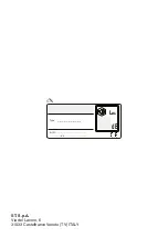
Write the identification data of the
machine in the specific space on the
label on the back of the cover page.
IMPORTANT
Quote the information on
the product identification label whenever you
contact an Authorised Service Centre.
IMPORTANT
An example of the
Declaration of Conformity is provided
on the last pages of this manual.
3.4 MAIN COMPONENTS
The machine is composed of a series
of main components that have the
following functions (Fig.1 ):
A. Power unit: it drives the rotor.
B. Blower tube: it is the component through
which the air flow is discharged.
C. Handgrip: it makes it possible
to control the machine.
D. Battery
(if it is not supplied with the machine,
see chapter 15 “accessories on request”)
:
device that supplies electric current to the
tool; its specifications and regulations for
use are described in a specific manual.
E. Battery charger
(if it is not supplied with
the machine, see chapter 15 “accessories
on request”)
: device used to recharge the
battery; its specifications and regulations
for use are described in a specific manual.
4. ASSEMBLY
IMPORTANT
The safety regulations
to follow are described in chap. 2. Strictly
comply with these instructions to avoid
serious risks or dangers.
For storage and transport purposes, some
components of the machine are not installed
in the factory and have to be assembled after
unpacking. Follow the instructions below.
Unpacking and completing the
assembly should be done on a flat and
stable surface, with enough space for
machine handling and its packaging,
always making use of suitable equipment.
Do not use the machine until all the
instructions provided in the “ASSEMBLY”
section have been carried out.
4.1 ASSEMBLY COMPONENTS
The packaging includes assembly components.
4.1.1 Unpacking
1. Carefully open the packaging, paying
attention not to lose components.
2. Consult the documentation in the
box, including these instructions.
3. Remove all the unassembled
parts from the box.
4. Remove the machine from the box.
5. Dispose of the box and packaging in
compliance with local regulations.
Before assembling, make sure the
battery is not inserted in its housing.
4.1.2
Assembly / disassembly
of the blower tube
1. Align the blower tube compartment (Fig. 3.A)
with the protrusion (Fig. 3.B) of the air outlet.
2. Push the pipe (Fig. 3.A) and rotate it by 90°
counterclockwise to hook it firmly in place.
– To remove the pipe, turn
clockwise and slide it out.
IMPORTANT
Stop the machine and
always remove the battery (paragraph 7.2.2)
whenever the blower tube is removed.
5. CONTROLS
5.1 THROTTLE SWITCH
The throttle control (Fig. 4.A) starts/
stops the machine and simultaneously
engages/disengages impeller rotation.
To start, press the throttle control and wait
2-3 seconds until the machine starts.
Summary of Contents for BL 40 Li
Page 4: ...A E D B C 1 Type WA L dB L Made in China s n Art N 1 4 2 3 6 7 5 2 ...
Page 5: ...A B A B 3 4 B A 5 6 B A B A 7 8 ...
Page 6: ...A 9 10 11 ...
Page 27: ...EXAMPLE ...
Page 28: ...EXAMPLE ...
Page 30: ...ST S p A Via del Lavoro 6 31033 Castelfranco Veneto TV ITALY dB LWA Type s n Art N ...


