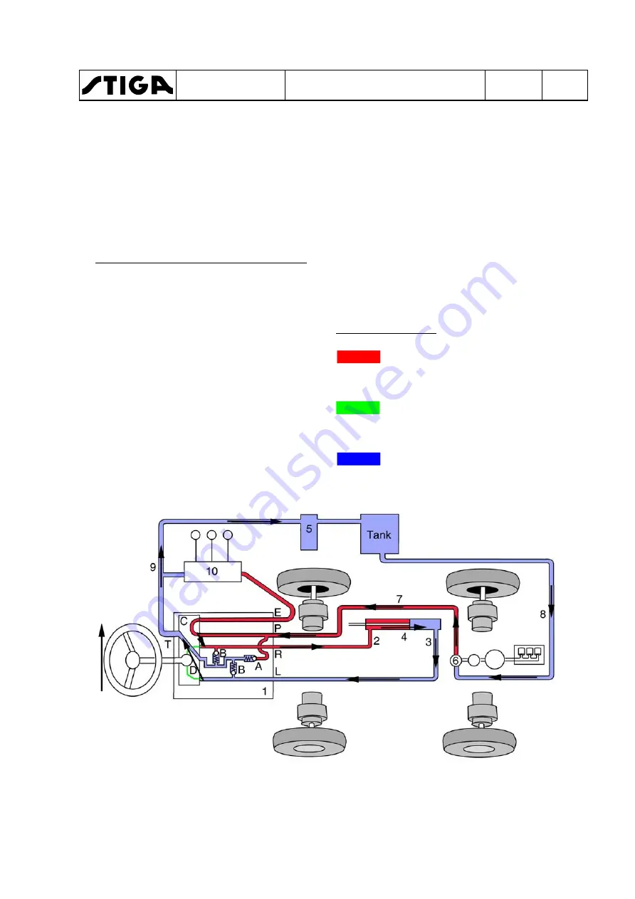
Stiga 13-7454-11 Workshop Manual Download Page 58

Steer to the right 

1.  Power steering servo containing the 

following: 
A. Pressure relief valve 
B. Safety valves 
C. Control module 
D. Oil pump 
Connections on power steering servo 
P. Unregulated input from hydraulic 
pump for external hydraulics. 
T. Output to the tank for tramp oil and 
return oil from the passive side of the 
steering cylinder when steering. 
E. Output to other external hydraulics. 
L. Output to steering cylinder. Pres- 
sure when steering to left. 
R. Output to steering cylinder. Pres- 
sure when steering to right. 

2, 3Pressure lines for transferring steer- 

ing force. 

4.  Steering cylinder. 
5.  Collector block. 
6.  Pump for external hydraulics, integrat- 

ed with the drive pumps. 

7.  Pressure line. 
8.  Suction line. 
9.  Tramp oil line and return line. 
10.External hydraulics. 
Colour - Pressure 

Red displays the supply pres- 

sure to the power steering servo 

and external hydraulics. 
Green can be both the pressure 

line and the return line, depend- 

ing on the movement. 
Blue displays the atmospheric 

pressure in the oil reservoir and 

lines. 


WORKSHOP MANUAL

TITAN

Chapter

4 - Hydraulic system 

EDITION

2018

Page

 5

6


Summary of Contents for 13-7454-11

Page 1: ...Titan 2013 2019 WORKSHOP MANUAL...

Page 2: ...use of the illustrations or duplication reproduction or translation even partial of the texts in this document may be made without explicit authorisation TABLE OF CONTENTS 1 General instructions 2 Ch...

Page 3: ...em Chapter 4 Hydraulic system Chapter 5 Control cables Chapter 6 Electrical system WORKSHOP MANUAL TITAN Chapter 1 General instructions EDITION 2018 Page 1 Contents 1 1 Introduction 2 1 1 1 Contingent...

Page 4: ...Symbol general warnings is a subheading to 1 2 Safety precautions and is included under this heading When referring to headings only the number of the heading is normally specified For ex ample See 1...

Page 5: ...aising Before work under the machine can be carried out the lifting equipment or jack capacity must be checked WORKSHOP MANUAL TITAN Chapter 1 General instructions EDITION 2018 Page 3 1 2 1 Symbols ge...

Page 6: ...cted by this guarantee 1 3 2 Conditions of the guarantee The guarantee card must be filled in with all information and then sent to Stiga or to the Stiga dealership In the event of a claim a record of...

Page 7: ...s are supplied as fully assembled as possible Thanks to this final assembly after deliv ery is quick and easy Note The machine must remain on the pallet while it is unpacked and as sembled 1 4 1 Assem...

Page 8: ...g order there is a risk of a short circuit and damage to the battery If the cables are switched it can result in damage to the alternator and battery The engine must never be run with the batterydisco...

Page 9: ...he disengagement lever is in the inner position Refer to the machine s instructions foruse Check that the distance from the centre of the wheel to the ground is the same for all 4 wheels If not adjust...

Page 10: ...s No unusual noise 1 5 2 Electric safety check Status Action Result The clutch brake pedal not depressed PTO not activated Attempt to start The engine should not start The clutch brake pedal depressed...

Page 11: ...terval Water separator check 50 in the instructions for use paragraph maintenance Filter in water separator cleaning Fuel filter replace 400 Tyre pressure check adjust Engine oil filter change 50 12 2...

Page 12: ...es equipped with air conditioning system The air conditioning system uses a refriger ant gas type R134a The quantity used to fill a new system is 0 9 kg The charging station must be connected to the s...

Page 13: ...3000 rpm 3000 rpm 3000 rpm Idle speed 1400 rpm 1400 rpm 1400 rpm 1400 rpm Lower temperature limit C 20 20 20 20 Cold start assistance Yes Yes Yes Yes Emission standards Eu Stage 3A 97 68 EC Eu Stage 3...

Page 14: ...in 125 bar 10 5 l min 125 bar 10 5 l min 125 bar PTO pump flow pres sure 42 l min 220 bar 42 l min 220 bar 42 l min 220 bar 42 l min 220 bar Air filter Type 5 Double filter dry 5 Double filter dry 5 D...

Page 15: ...es Yes Yes Lighting front Yes Yes Yes Work light ing Yes Work light ing ROPS Yes Yes Cab with heating Yes Yes Cab with AC Yes Hour meter Yes Yes Yes Yes Volumes L Volume in the fuel tank 42 42 42 42 O...

Page 16: ...red implements Example If a machine weighs 1000 kg the weight must not be less than 300 kg over the least laden axle Lift force Note Important Axle load must not exceed 900 kg on the most laden axle D...

Page 17: ...WORKSHOP MANUAL TITAN Chapter 1 General instructions EDITION 2018 Page 15...

Page 18: ...WORKSHOP MANUAL TITAN Chapter 1 General instructions EDITION 2018 Page 16...

Page 19: ...WORKSHOP MANUAL TITAN Chapter 1 General instructions EDITION 2018 Page 17...

Page 20: ...acing filters etc re fer to the instruction manual supplied with the machine Instructions for use are available at the GGP Parts Service website http www ggppartsandservice com For more product inform...

Page 21: ...ifferent pieces of equip ment and how they are repaired WORKSHOP MANUAL TITAN Chapter 2 Chassis and bodywork EDITION 2018 Page 19 Contents 2 1 Description 20 2 2 Removal Installation of covers 21 2 2...

Page 22: ...ion also means that an op timal unmown circle is created when the machine is operated at full lock The articulated frame also pivots vertical ly 10 when the machine is straight ahead and 2 at full loc...

Page 23: ...rewing the five screws B 3x C 2x behind the side covers Remove the upper coverby unscrew A ing the screws D 4x and B 3x same screws as the rear engine cover Remove the front cover byreleasing the lock...

Page 24: ...the screws B 5x for machines with cab machines without a cab have screws B 5x C 2x securing the cov er When reinstalling use silicone spray along the sealing trim 3 If necessary remove the other cover...

Page 25: ...edi ately after operation Allow the engine to cool before draining the coolant 2 Place a container under drainscrew A Then drain the radiator by unscrew ing the drain screw 3 Install the vacuum pump a...

Page 26: ...e hose to the return oil filter is visible and discon nect the fan from the radiator Use a 32 mm socket 10 Unscrew the remaining screws G 2x that secure the radiator from under neath Use a 13 mm socke...

Page 27: ...drain screw D is closed and sealed 4 Check that all the hoses in the cooling system are intact and sealed 5 Unscrew the radiator cap A 6 Slowly fill the radiator with coolant Air bubbles must not for...

Page 28: ...See image Changing door window 1 Remove the door cylinder from the door frame 2 Remove the whole door by unscrew ing the screws B 2x 3 Remove the door handle unscrew the screws C 2x D 2x E 4 Unscrew t...

Page 29: ...ndscreen wiper motor 1 Remove the screw on the plastic cov er that covers the windscreen wiper motor 2 Unscrew the two wiper arms that are each secured by a nut 3 Undo the lower screws A 2x 4 Slacken...

Page 30: ...ipped beam These must be set according to lo cal regulations A guideline is shown in the image below The same applies for machines without cab with road kit 104cm 2m 82cm 2m WORKSHOP MANUAL TITAN Chap...

Page 31: ...lifting eyes 12 mm with the DIN 580 standard 8 Slacken off the front screws C 4x that are below the windscreen inside the cab 9 Slacken off the screws D 8x that are 4x and 4x on each side of the seat...

Page 32: ...ints are shown in the figures on the following pages Object Lubrication nipples action Fig ure Lifting fork turning 1 lubrication nipple A Lifting fork up down 2 lubrication nip ples B Lifting cyl ind...

Page 33: ...chother This chapter contains a short description of how the steering works how repairs are car ried out and how wear components of the steering system are adjusted WORKSHOP MANUAL TITAN Chapter 3 Ste...

Page 34: ...protection on each side of the plastic cover and remove the screws inside Then twist the whole cover off C Lift the rubber mat off the floor D Then unscrew the screws B 4x on each side of the duct and...

Page 35: ...espective sockets Note Take care to mark the hoses be fore removal 8 Slacken off and remove the hoses Take care to use plugs for both the hose and the unit so that dirt cannot penetrate the system No...

Page 36: ...ing wheel byknock ing out the locking pin 8 Mark the position of the five hydraulic hoses that are connected under the power steering servo The letters in the figure are stamped on the bottom beside t...

Page 37: ...housing A 2 Choke valves S Remove the plastic plugs from the adjustment screws and unscrew using a 6 mm Allen key Shake out the two springs and two valve balls Unscrew the valve seats with a 3 mm Alle...

Page 38: ...n shaft C and ensure that it aligns with pin K 12 Install O rings 5 on both sides of gear wheel N ensure that the O rings are lubricated before installation 13 Align gear wheel N and propshaft L so th...

Page 39: ...WORKSHOP MANUAL TITAN Chapter 3 Steering system EDITION 2018 Page 37...

Page 40: ...WORKSHOP MANUAL TITAN Chapter 3 Steering system EDITION 2018 Page 38...

Page 41: ...e the circular lockingrings Note In this position all surfaces must be visually checked for scratches and other contamina tion take care not to mark the pipe can be difficult to polish out 9 Grasp the...

Page 42: ...der torqued the pis ton can work loose over time 10 Apply a little oil around the pipe on the piston seal and the collar O ring 11 Install the piston and collar in the pipe 12 Install the circular loc...

Page 43: ...the piston shaft so that it is free of contamination 4 Polish off the adhesive from the threads on the shaft Clean using sol vent 5 Apply a little oil inside the collar Note Do not heat the sealing su...

Page 44: ...e 243 to the collar threads 13 Then thread on the collar 15 Ready for use Note Any guarantees are invalidated if the cylinder has been disman tled WORKSHOP MANUAL TITAN Chapter 3 Steering system EDITI...

Page 45: ...Chapter 4 Hydraulic system EDITION 2018 Page 43 Contents 4 1 Safety 44 4 2 Configuration 44 4 3 Description of drive system 45 4 3 1 Physical description 45 4 3 2 Function descriptio 48 4 4 Descripti...

Page 46: ...4 2 Configuration The machines have hydraulically pow ered PTO and are equipped with a hy draulic system with three functions as below Drive system External hydraulics PTO drive The different systemso...

Page 47: ...axle 13 14 Non return valves 15 By pass valve 16 Equalisation channels integrated in the left wheel motors front and rear 17 Line for tramp oil flow 18 Pressure limiter valve 2 5 bar E Engine F Tank...

Page 48: ...physical components of the wheel motors are as follows 1 Wheel axle 2 Thread for lifting eye 3 Hydraulic motor 4 Main connections 5 Draining for hydraulic motor 6 Drain plug for planetary gear 7 Plug...

Page 49: ...ic pumps are inte grated to one unit A Pump for the external hydraulics This pump is not part of the drive system B Main pump charge pump C Drive system main pump A B C WORKSHOP MANUAL TITAN Chapter 4...

Page 50: ...n flow between left motor 12 By pass line front axle 13 14 Non return valves 15 By pass valve 16 Equalisation channels integrated in the left wheel motors front and rear 17 Line for tramp oil flow 18...

Page 51: ...n left motor 12 By pass line front axle 13 14 Non return valves 15 By pass valve 16 Equalisation channels integrated in the left wheel motors front and rear 17 Line for tramp oil flow 18 Pressure limi...

Page 52: ...he leakage Prioritising driving The motors on the same axle are con nected in parallel The front wheel motors are connected in series to the rear wheel motors The rear wheel motors are first in the ci...

Page 53: ...e wheels are turned The re sistance is not zero in the system when the by pass valve is open Therefore it is only permitted to push the machine for short distances with an open by pass valve for examp...

Page 54: ...Pres sure when steering to left R Output to steering cylinder Pres sure when steering to right 2 3 Pressure lines for transferring steer ing force 4 Steering cylinder 5 Collector block 6 Pump for exte...

Page 55: ...e The control module has an integrated function that always prioritises the steering in those cases when the steering and the external hydraulics are used at the same time D Oil pump The power steerin...

Page 56: ...dule D Oil pump Connections on power steering servo P Unregulated input from hydraulic pump for external hydraulics T Output to the tank for tramp oil and return oil from the passive side of the steer...

Page 57: ...to left R Output to steering cylinder Pres sure when steering to right 2 3Pressure lines for transferring steer ing force 4 Steering cylinder 5 Collector block 6 Pump for external hydraulics integrat...

Page 58: ...to left R Output to steering cylinder Pres sure when steering to right 2 3Pressure lines for transferring steer ing force 4 Steering cylinder 5 Collector block 6 Pump for external hydraulics integrat...

Page 59: ...o steering cylinder Pres sure when steering to right 2 3Pressure lines for transferring steer ing force 4 Steering cylinder 5 Collector block 6 Pump for external hydraulics integrat ed with the drive...

Page 60: ...ow the con tours of the ground Use the float ing position when carrying out work Raising Move the lever to the rear position until the implement is in the highest position trans port position Then rel...

Page 61: ...and further description of the components 1 Pressure relief valve 2 Mechanically affected non return valve 3 Mechanically affected non return valve 4 Limit valve lowering 5 Collector block 6 By pass...

Page 62: ...revent movement 3 under the implements own weight the oil flow is stopped by these valves To 2 allow oil flow when the implement is to move in the blocked direction the valves are mechanically operate...

Page 63: ...line Oil flows from the control module and through the by pass line 6 The oil then flows back to the tank via the collector block Colour Pressure Red displays the supply pres sure to the external hyd...

Page 64: ...l on the other side of the piston is pressed back to the tank via the valve Ls and the collector block 2 Mechanically affected non return valve 4 Limit valve lowering 5 Collector block 6 By pass line...

Page 65: ...lays the atmospheric pressure in the return lines The by pass line is blocked in valve Ls Oil flows from the control module and through the valve Ls Valve 1 limits the pressure to 35 bar to protect th...

Page 66: ...cks itself automatically in floating position Oil flows from the control module and through the by pass line 6 The oil then flows back to the tank via the collector block Valve 2 is opened mechanicall...

Page 67: ...ack to the socket through valve 3 valve Aux1s collector block 5 and back to the tank Valve 3 is opened mechanically by Aux1s 3 Mechanically affected non return valve 5 Collector block 6 By pass line C...

Page 68: ...nt Then back to the socket through valve Aux1s the collector block 5 and back to the tank Valve 3 is opened by the oil pressure 3 Mechanically affected non return valve 5 Collector block 6 By pass lin...

Page 69: ...rough valve Aux2s collector block 5 and back to the tank Hydraulic sockets Aux2 front or Aux2r rear are selected by electric valve 7 This means that only one implement can be controlled connect to eit...

Page 70: ...rough valve Aux2s collector block 5 and back to the tank Hydraulic sockets Aux2 front or Aux2r rear are selected by electric valve 7 This means that only one implement can be controlled connect to eit...

Page 71: ...r block 6 Brake valve 7 Oil cooler 8 Tramp oil line P Hydraulic pump PTO1 Hydraulic socket PTO1s Switch T Tank Colour Pressure Red displays the supply pres sure to the implement Blue displays the atmo...

Page 72: ...he brake valve minimises the imple ment stop time 7 Radiator The PTO oil always passes the oil cooler when the engine is running Because the same oil is used fordriv ing the hydraulic oil is kept at a...

Page 73: ...witch T Tank Colour Pressure Red displays the supply pres sure to the implement Blue displays the atmospheric pressure in the return lines The solenoid is unpowered and the slide is in wait mode Left...

Page 74: ...urn lines The solenoid is activated using switch PTO1s and the slide closes the left valve and opens the right valve The pump pumps oil that is forced through the implement s hydraulic motor because t...

Page 75: ...ed off and the slide returns to stand by mode Left valve is open and right valve is closed The pressure in the supply line disap pears but an implement tool continues to rotate due to the kinetic ener...

Page 76: ...t A3 New filter The filter must always be replaced when changing the oil A4 Spring A5 Gasket check that the gasket is intact A6 Cap 10 After filling the oil start the engine and Note It is very import...

Page 77: ...ating temper ature with varied workload so that the hydraulic oil warms up 2 Place the machine on a level surface 3 Clean carefully around the oil plugs A and B 4 Place a container under the oil drain...

Page 78: ...and slide up the tensioner device C to its max D position then tighten the upper screw D for the tensioner device to maintain B C its new position 5 Remove the pulley E by locking the starter crown wh...

Page 79: ...t off the belts and re move them by threading them out be tween the carrier plate and the flywheel Assemble all parts in the reverse order Tension the belts between steps 4 5 when installing the belts...

Page 80: ...t between the carrier plate and the flywheel Assemble all parts in the reverse order Adjust the belt as necessary see 4 7 6 4 7 5 Adjusting drive belts C V belt Poly V 1 Screw an M8 80 screw into A Sl...

Page 81: ...uum pump A 5 Slacken off and disconnect the hy B draulic hoses Before slackening off the hoses they should be marked to ensure that they are reinstalled in the correct position Make sure that plugs ar...

Page 82: ...height or the height position of the implement follow the pro cedure below by doing in sequence 1 Check of the cutting deck hydrau lic cylinder making sure that it has no internal leakages valid only...

Page 83: ...ssible to swap it by using one of the cylinders for the two flaps The flaps can accept a small leakage on the cylinder If the arrow has not changed position then the cylinder is ok and step 2 must be...

Page 84: ...mp is developed to cre ate a vacuum in the tank to facilitate at service and repairs affecting the hydrau lic system Connection 1 Remove the engine covers See 2 2 1 2 Unscrew the cap for tank vent val...

Page 85: ...ted 3 Adjust the pressure using valve B and read off the pressure on the pressure gauge Adjusting brake pressure 1 Connect a pressure gauge to meas urement output MT1 2 Attach a cutting deck start the...

Page 86: ...4 10 Hydraulic diagram WORKSHOP MANUAL TITAN Chapter 4 Hydraulic system EDITION 2018 Page 84...

Page 87: ...apter 5 Control cables EDITION 2018 Page 85 Contents 5 1 Description 86 5 1 1 General 86 5 1 2 Cable holders 86 5 1 3 Angle joints 86 5 2 Control cable 88 5 2 1 Description 88 5 2 2 Dismantling 88 5 2...

Page 88: ...ock nut or angle joint at one or two ends Note When adjusting at least 5 threads must be screwed in Cable maintenance Apply a few drops of oil or use spray grease in the ends of the cable housings two...

Page 89: ...ation Adjustment 1 Loosen nut 3 with an 8 mm spanner 2 Dismantle the angle joint as de scribed above 3 Screw the joint body in the desired di rection on the cable screw Move nut 3 on the screw if nece...

Page 90: ...cable transfers both thrust and trac tive forces 5 2 2 Dismantling 1 Disconnect the cable at hydraulic pump arm A and the adjuster nuts B at the hydraulic pump mounting 2 Disconnect the cable at the f...

Page 91: ...5 Adjustment It is very important that the control cable is correctly adjusted otherwise the maxi mum forward and backward positions cannot be reached as well as exposing the cable to greater stresse...

Page 92: ...nt from the parking brake pedal to the brake levers on the wheel motors The brakes are part of the machine safety system It is very important that the brake cables are fault free and correctlyadjusted...

Page 93: ...previously Also see the image below 3 Adjust the cable See 5 3 5 5 3 4 Check Check that the cable can move easily in the housing along the whole length of the stroke Check that the cable is free of sh...

Page 94: ...n the brake is not activat ed 2 Activate and lock the brake 3 The spring body length must be 42 mm 4 Adjust so that all four springs have the dimensions above Attention The cables can be adjusted at b...

Page 95: ...simultaneously pulling it upwards 4 Slacken off the screws B 4x with nuts 5 Remove the cable from the motor by locking screw C and the adjuster nuts D 6 Note how the cable is routed so that the new c...

Page 96: ...netrate Check that the end seals are intact 5 4 5 Adjustment 1 When the throttle control is in neutral position it must not be possible to B move the arm closer to the idle posi tion A 2 Put the throt...

Page 97: ...2 1 The starter motor does not rotate 97 6 2 2 The startermotor rotates but the engine does not start 97 6 2 3 Battery discharges repeatedly 99 6 2 4 The engine does not stop 99 6 2 5 The PTO does not...

Page 98: ...ectrical cables can cause unnecessary wear to the compo nents This can lead to short circuits damage to plastic protection paintwork etc 6 2 Fault tracing Warning Do not wear rings bracelets necklaces...

Page 99: ...ring metering No Is there 12 V on connection B on the safety relay Yes No Is there 12 V between the red and brown cables on the pedal switch Yes No Temporarily connect a cable between G yellow cable o...

Page 100: ...ve And Yes Is there 12 V on the red cable on the shut off valve No No Do other electrical functions operate when the ignition is activated Yes For venting the fuel system see 5 12 in the user instruct...

Page 101: ...on connection IG on the alternator when the ignition is activated No 6 2 4 The engine does not stop Does all other equipment switch off when the ignition is switched off Yes No Replace battery Replac...

Page 102: ...TO relay Replace adjust the micro switch Is there 12 V between D5 violet cable and D6 brown cable on the front sec tion of connection D when the PTO is activated Ye No Is there 12 V between D5 violet...

Page 103: ...adjustment does not func tion 6 2 7 The engine can be started without the parking brake depressed Yes Replace the engine on the cutting deck Connect a voltmeter to the engine con nections in the cutt...

Page 104: ...reader socket rear Connect a voltmeter to 31 ground and 54 orange Then to 31 ground and 58 black Activate the switch between its posi tions Does the voltmeter show 12 V at both meterings Yes No Front...

Page 105: ...is built up and display some of the cables and explain what the various connections are for The cables that the workshop manual covers are Cable Rear cable harness left Rear cable harness right Front...

Page 106: ...6 3 2 Cable WORKSHOP MANUAL TITAN Chapter 6 Electrical system EDITION 2018 Page 104...

Page 107: ...A3 S tarter A2 G enerator L A1 Hyd olje temp B9 G round B8 B7 B B6 B5 B4 Brake B3 P os B 2 Direction flash R H B 1 Direction flash LH Left cable 1 2 3 4 5 6 7 8 9 1 2 3 4 5 6 7 8 9 WORKSHOP MANUAL TIT...

Page 108: ...res sure C5 G lowing C4 Cruise control C3 Cruise control C 2 S andspreader 58 C 1 S andspreader 54 D9 12V D8 R adio D6 P TO D5 P TO D4 B rake D3 P osition D2 D1 Direction flash R H Right cable WORKSHO...

Page 109: ...Low beam F3 Direction flash R H F2 P os F1 Direction flash LH G G9 Ground G8 G7 G6 G5 G 4 P ilot lamp direction flas h G3 12V Arm G 2 Light control switch direction flash G 1 Light control switch low...

Page 110: ...ch E3 P edal switch E2 P edal switch E1 P edal switch F9 G round F8 F7 Hazzard sw F6 Hazzard sw F 5 Front lights F4 Low beam F 3 Direction flash R H F2 P os F 1 Direction flash LH G9 Ground G8 G7 G6 G...

Page 111: ...5 F6 6 F7 7 F8 8 SWEEPER SWITCH ROTATING SWITCH T2 LIGHT T3 SWITCHES SCREEN WATCHING PUMP J3 2 J3 1 J3 3 J3 4 J3 5 J3 6 J3 9 RED BLACK RED BLACK J10 J11 J4 1 J4 2 J4 3 J4 6 J4 4 J12 SCREEN WASHING PUM...

Page 112: ...TO is not activated and someone sits on the seat 2 Voltage in position C Receives current through the fuse and the pedal switch when the pedal for the parking brake is depressed when the ignition is o...

Page 113: ...n el Remove the right side cover if necessary also remove the control panel See 2 2 2 for description of dismantling Relay locations The relays are located under the front side cover on the right side...

Page 114: ...is in the roof of the cab and contains the fuses for the cab s electrical functions The fuse box is under the con trol panel in the roof and is accessible by removing the control panelscrews Designat...

Page 115: ...3 30 A Turn signal lamps A4 10 A Spare A5 Parking lights Horn Dipped beam relay A6 10 A Hazard warning lights A7 10 A AC A8 10 A Indicator lamps Buzzer hold valve transport position B1 10 A Cutting he...

Page 116: ...rtain connections have 2 fixing hooks 3 Press the fixing tabs on both sides of the switch against the switch Use a screwdriver or similar to slide the switch up See figure 6 5 4 Replacing switch contr...

Page 117: ...Other types of connectors may require special tools for removal Warning No metal from the cable may be visible outside the screw con nection Too long stripped ca bles can cause short circuits or fire...

Page 118: ...ont part of the switch PTO engages The symbol will light up 2 Press the rear part of the switch PTO disengages Switch A3 12V The switch hasthree positions and can be used for the sand spreader for exa...

Page 119: ...arning beacon that is po sitioned on the roof of the ma chine Work lighting B3 Obs Follow applicable laws regard ing use of the work lighting The switch is located in the roof and is used to switch th...

Page 120: ...6 7 Wiring diagram WORKSHOP MANUAL TITAN Chapter 6 Electrical system EDITION 2018 Page 118...

Page 121: ...WORKSHOP MANUAL TITAN Chapter 6 Electrical system EDITION 2018 Page 119...

Page 122: ...WORKSHOP MANUAL TITAN Chapter 6 Electrical system EDITION 2018 Page 120...

Page 123: ...STIGA S p A Via del Lavoro 6 31033 Castelfranco Veneto TV Italy www stiga com...

Reviews: