INSTRUCTION MANUAL VIGIBELT
®
TOUCH ATEX (II 2 D)
GB
–
4/4
- VER. 01/16 - N° DOC BE0455041
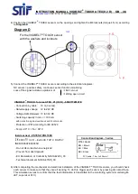
4) Position the VIGIBELT
®
TOUCH sensors on the openings and tighten the M6 locknuts (torque 4 N.m) according
to
Diagram-D
.
5) Connect the VIGIBELT
®
TOUCH sensors according to the electrical diagrams:
NC sensor = positive safety, continuous sensor function monitoring
Loss of the signal indicates a problem of
Belt run-out
Wiring open circuit
6) After completing the mechanical and electrical installation of the VIGIBELT
®
TOUCH sensors, you should check
each sensor to make sure that they are all working. To do this, trigger each sensor by pressing its contact face.
This simulation serves to confirm that the fault information is transmitted to the monitoring system (monitoring M-
JET, supervisor PLC).
VIGIBELT
®
TOUCH for area ATEX 21 (II 2 D) - 55KVT72616TE
- Connection by cable:
10 m (3 wires)
- Rated supply voltage: 12 to 24V DC
- Voltage limits (incl. wave): 10 to 36V DC
- Switching capacity in mA: <= 100 mA
with protection against overloads and short-circuits
- Protection - IP67 according to IEC 60529
- Temp: -20° C < Ta < 60° C
Connection diagram - 3 wires
Wire colours
BN = Brown
BU = Blue
BK = Black
PVC cable - 10m; 3x0.34mm²
BN
BK
BU
+
-
NC/PNP
Diagram D
Fix the VIGIBELT
®
TOUCH sensor
with the washers and locknuts
Inside sensor - XS7E1A1PBL10EX
0080
II 2 D
– Ex tb IIIC T90° C Db IP67
INERIS 06ATEX0065X
- Do not disconnect when energized
- Prevent from dust deposits
- EU Declaration of Conformity Nr/S1A42203_03
- Technical document Nr/S1A41508_00


