INSTRUCTION MANUAL VIGIBELT
®
TOUCH ATEX (II 2 D)
GB
–
3/4
- VER. 01/16 - N° DOC BE0455041
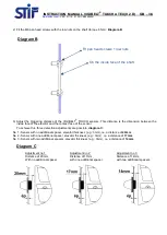
2) Fit the M6 pan head screws with the low nuts on the shaft (torque 6 N.m):
Biagram-B
.
3) Adjust the triggering distance of the VIGIBELT
®
TOUCH sensors. This distance is the dimension between the
inside face of the elevator and the contact face of the sensor.
To achieve this, three detection adjustments are possible,
diagram-C
:
No 1 - Sensor with no additional spacer, elevator thickness (e.g.: 3mm), i.e. a distance of
20mm
No 2 - Sensor with one additional spacer, elevator thickness (e.g.: 3mm), i.e. a distance of
17mm
No 3 - Sensor with two additional spacers, elevator thickness (e.g.: 3mm), i.e. a distance of
14mm
Diagram B
On the inside face of the shaft
Fit pan head low nuts
Diagram C
Adjustment no 1
Distance of 20mm,
With no additional spacer
Adjustment no 2
Distance of 17mm,
with one additional spacer
Adjustment no 3
Distance of 14mm,
with two additional spacers


