background image

9

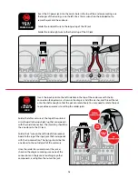
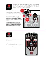
Next, we’re going to add a bunch of resistors to our printed circuit board. As in the 
previous step, you’ll find an outline of each resistor and its value printed in their proper 
location on the printed circuit board. Match resistors to the values on the printed circuit 
board and solder in place.

Resistors are not polarized, so it doesn’t matter which lead goes in which eyelet. 

INSTALL 19 

RESISTORS

3

220Ω resistor (1)


#7353


2.4K resistor (1)


#7387


Red   Red   Black   Black   Brown

Red   Yellow   Black   Brown   Brown

1K resistor (4)


#7357


Brown   Black   Black   Brown   Brown

4.7K resistor (1)


#7359


Yellow   Violet   Black   Brown   Brown

100Ω resistor (1)


#7352


Brown   Black   Black   Black   Brown

10K

10K

10K

10K

10K

10K

10K

10K

470K

100K

1M

20K

22K

22K

22K

1K

47K

47K

220K

220K

4k7

1K resistor (1) 

#7357 

BrownB lack BlackB rown Brown

BrownB lack BlackO range Brown

100K resistor (1) 

#7365


Yellow Purple BlackR

ed

Brown

47K resistor (3) 

#7369 

RedR

ed

BlackO range Brown

220K resistor (2) 

#7381 

BrownB lack BlackY ellowB rown

1M resistor (1) 

#7367 

Yellow Purple BlackO range Brown

470K resistor (2) 

#7382 

RedR

ed

BlackR

ed

Brown

22K resistor (3) 

#7379 

BrownB lack BlackR

ed

Brown

10K resistor (8) 

#7362 

RedB

lack BlackR

ed

Brown

20K resistor (1) 

#7397


Yellow Purple BlackB rown Brown

4.7K resistor (1) 

#7359


Resistors have a low profile, sitting closer to the board 
than taller components, so installing these now will make 
installing other parts easier later on. 

510K resistor (2)


#7366


Green   Brown   Yellow   Gold

20K resistor (1)


#7397


Red   Black   Black   Red   Brown

2.2M resistor (1)


#7368


Red   Red   Black   Yellow   Brown

10K resistor (7)


#7362


Brown   Black   Black   Red   Brown

Summary of Contents for SCREAMER

Page 1: ...ly change your tone The idea of this circuit is not to distort the signal on its own but to push the preamp tubes of your amp into screaming distortion POWER This pedal requires a standard 9V DC center negative power supply not included and consumes less than 100mA There s no battery option SCREAMER PEDAL KIT INSTRUCTION GUIDE 1J63 22J63 1J63 4558D IN GND SW OUT TECHNICAL SUPPORT If you have any q...

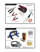
Page 2: ...lder 0505 Wire Cutter 1607 Long nose pliers 1610 Fine gauge Wire Stripper 1606 Guitar Tech Screwdriver and Wrench Set 3693 Not pictured Clear silicone adhesive and spray finish PC Board Holder 0500 Magnifying glass or OptiVISOR 1685 Soldering Aids 0521 Multimeter 3607 3M Gold Fre Cut Sandpaper 220 grit 5097 ...

Page 3: ... Violet Black Brown Brown Green Brown Yellow Gold PARTS LIST 1µF capacitor 2 7314 1uF 100nF capacitor 2 7304 1J63 2C1815 transistor 2 7516 CEN 2C 1815 27nF capacitor 1 7325 27n63 220nF capacitor 1 7305 180nF capacitor 1 7476 μ18J63v 22J63 1N914 rectifier diode 3 7521 1N5817 rectifier diode 1 7522 10µF capacitor 1 7338 47µF capacitor 2 7478 47uF 51pF capacitor 1 7301 510 10 uF 5mm white LED 1 7422 ...

Page 4: ...e foam tape square 4 7560 5mm LED mounting bezel 1 7432 Control knob 3 7501 2 1mm DC power jack 1 7468 JRC4558D op amp integrated circuit 1 7446 Integrated circuit socket 1 7484 4558D VOLUME DRIVE TONE 1 4 mono jack 2 4652 Printed circuit board 1 Sticker sheet 1 Breakout board 1 IN GND SW OUT Pre drilled enclosure top 1 Pre drilled enclosure bottom not pictured 1 Screws not pictured 4 ...

Page 5: ...5 100 000 5 BLUE 6 6 6 1 000 000 25 VIOLET 7 7 7 10M 1 GRAY 8 8 8 01 SILVER WHITE 9 9 9 1 GOLD 0 SOLDERING MORE HELPFUL SOLDERING TIPS AND TRICKS Keep your soldering tip clean by wiping it often on a damp sponge Also keep it tinned by occasionally melting a little solder onto it Don t blow on the hot solder or touch anything until the joint has cooled completely A good solder joint is shiny a sign...

Page 6: ...nd will be shorter than the positive lead The positive lead of an electrolytic cap will be longer and won t have the stripe on that side Installing capacitors with the polarity backwards will make the circuit malfunction and quickly destroy the capacitor even causing it to explode CAPACITORS The two main uses of capacitors are to store electricity and to block the flow of DC current Capacitor valu...

Page 7: ...nd pressure is required to perceive a smooth transition LEDs LED stands for Light Emitting Diode and functionally LEDs are very similar to regular diodes LEDs are most often used as indicator lights in pedals They are polarized just like diodes and electrolytic capacitors and must be installed in the correct orientation to work The positive anode lead of the LED will be longer and the anode side o...

Page 8: ...ted on the printed circuit board 2N5089 1 To minimize redoing steps make sure you have a solid idea of the look and feel you re going for 2 Lightly sand the outside of the enclosure with 220 grit sandpaper and wipe clean any debris 3 Cover the holes from the inside with masking tape 4 On a piece of cardboard place the enclosure and bottom cover on scraps of wood to lift them off the cardboard when...

Page 9: ...0K 100K 1M 20K 22K 22K 22K 1K 47K 47K 220K 220K 4k7 1K resistor 1 7357 BrownB lack BlackB rown Brown BrownB lack BlackO range Brown 100K resistor 1 7365 Yellow Purple BlackR ed Brown 47K resistor 3 7369 RedR ed BlackO range Brown 220K resistor 2 7381 BrownB lack BlackY ellowB rown 1M resistor 1 7367 Yellow Purple BlackO range Brown 470K resistor 2 7382 RedR ed BlackR ed Brown 22K resistor 3 7379 B...

Page 10: ... 220nF capacitor 1 7305 27nF capacitor 1 7325 27n63 180nF capacitor 1 7476 μ18J63v 51pF capacitor 1 7301 510 The remaining capacitors below are not polarized However best practice is to solder these caps in place all facing the same direction when possible The three types of capacitors shown below are polarized and must be installed in the correct orientation Note the stripe running the length of ...

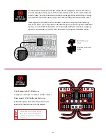
Page 11: ... with different op amps We ve supplied a JRC4558D op amp as in the TS 808 Tube Screamer You can explore different sounds by swapping op amps For example try the TL072CP Klon Centaur style op amp StewMac 7444 INSTALL THE OP AMP 6 2n2J630 TL072 4558D PT2399 PT2399 PT2399 echo audio processor 1 7490 4558D 4558D op amp 7446 1J63 22J63 1J63 4558D The kit comes with 24 of lead wire Cut the wire into eig...

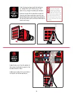
Page 12: ...to right Slide the lugs of the footswitch up through the bottom of the board Solder each lug to the breakout board around it If the lugs of the footswitch don t quite fit in the breakout board use a pair of pliers to gently bend the lugs of the footswitch until the breakout board slides over the lugs IN GND SW OUT IN G ND SW OUT You can use the pedal enclosure as a mount for the footswitch while y...

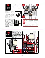
Page 13: ... the other parts on the printed circuit board This is especially important on the back of the tone pot TIME Once you ve removed any index pins and added the foam tape to the back of each pot use the pedal enclosure as a mount for the control pots while you solder the printed circuit board to them Just lay the enclosure face up and arrange the pots in their holes No need to fasten them with a nut f...

Page 14: ...nted circuit board is held in place by the control pots but the LED leads need to pass through their eyelets in the printed circuit board before the pots will pass through the enclosure Pass the longer positive lead of the LED through the eyelet marked A and the shorter negative lead through the eyelet marked K Next secure the pots by installing their shafts through the enclosure and slide washers...

Page 15: ...e 4 wire on the left side of the breakout board to the lug of the input jack that corresponds with the tip connection The tip lug should be the one closer to the outside wall of the enclosure Once the solder has cooled orient the jack as shown in the diagram making sure none of the connections on the jack are touching any other components and tighten the nut on the jack SHIELD SHIELD INSTALL THE D...

Page 16: ...to the DC jack Solder the 4 wire on the right side of the breakout board to the lug of the output jack that corresponds with the tip connection The tip lug should be the one closer to the outside wall of the enclosure Once the solder has cooled orient the jack as shown in the diagram making sure none of the connections on the jack are touching any other components and tighten the nut on the jack S...

Page 17: ... distortion all on its own TONE This is a standard issue tone control Turn it clockwise for more treble and turn it counter clockwise for more bass Although this is what your ear perceives the way the tone control actually works is by cutting bass as you turn the knob clockwise and cutting treble as you turn the knob counter clockwise POWER Use a standard 9 volt DC power supply with a 2 1mm negati...

Reviews: