10
INSTALL 5
CAPACITORS
4
10uF
10µF capacitor (1)
#7338
1µF capacitor (2)
#7314
10uF
1uF
47µF capacitor (2)
#7478
47uF
INSTALL 6
CAPACITORS
5
1u
+
1u
+
+
100u
+
10
u
+
100u
+
100u
1u
+
1u
+
1u
+
+
10
u
100pF
22n
22n
22n
22n
22n
22n
220n
2n2
1n
100n
100n
100n
100n
100n
100n
.0022µF capacitor (1)
#7324
.22µF capacitor (1)
#7305
.1µF capacitor (6)
#7304
100pF capacitor (1)
#7326
101J
100V
.001µF capacitor (1)
#7302
102J
2n2J630
.022µF capacitor (6)
#7317
.1J63
.22J63
1µF capacitors (5)
#7314
1uF
10µF capacitor (2)
#7338
100µF capacitor (3)
#7312
10uF
100uF
10K
1M
470K
100K
22K
1K
47K
220K
10K
10K
10K
10K
10K
10K
10K
470K
22K
47K
47K
220K
22K
4K7
10K
1M
470K
100K
22K
1K
47K
220K
10K
10K
10K
10K
10K
10K
10K
470K
22K
47K
47K
220K
22K
4K7
.1
J6
3
.22J63
.1
J6
3
10uF
.1J
63
100nF capacitor (2)
#7304
.22J
63
220nF capacitor (1)
#7305
27nF capacitor (1)
#7325
27
n63
180nF capacitor (1)
#7476
μ1
8J
63v
51pF capacitor (1)
#7301
51
0
The remaining capacitors below are not polarized. However, best practice is to solder
these caps in place all facing the same direction when possible.
The three types of capacitors shown below are polarized and must be installed in the
correct orientation. Note the stripe running the length of each cap; this identifies the
negative (–) lead (the negative lead is also shorter).
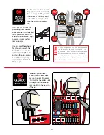
On the printed circuit board, each capacitor has a square-shaped eyelet marked positive (+).
The negative lead’s eyelet is round.


