


13
10
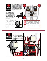
If any pot has an index pin
protruding from the case,
break it off before installation,
so the pot will mount flush
against the pedal case. Long-
nose pliers work well for
removing pins.
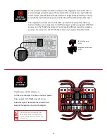
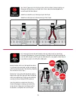
The last components to go onto
the printed circuit board are the
three control pots. They install
on the back of the board. Each
pot has three connecting lugs.
Note the orientation of each
pot.
INSTALL 3
POTS AND
ATTACH
FOAM TAPE
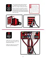
Use a piece of the adhesive
foam tape to insulate the
back of the pots from the
soldered leads of the other
parts on the printed circuit
board. This is especially
important on the back of
the tone pot.
TIME
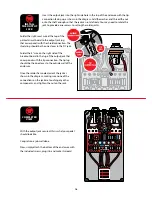
Once you’ve removed any index pins and added
the foam tape to the back of each pot, use the
pedal enclosure as a mount for the control pots
while you solder the printed circuit board to
them. Just lay the enclosure face-up and arrange the
pots in their holes. No need to fasten them with a nut
from the back if you don’t want to.
VOLUME
(B100K)
TONE
(B25K)
.1
J6
3
.22J63
.1
J6
3
4558D
IN GND SW OUT
SOLDER POTS
TO PRINTED
CIRCUIT BOARD
11
Solder the pots in place,
making sure the foam back
stays on the back of the pot.
This insulates the solder joints
on the printed circuit board
from shorting to the housing
of the pot.
DRIVE
(A500K)