1
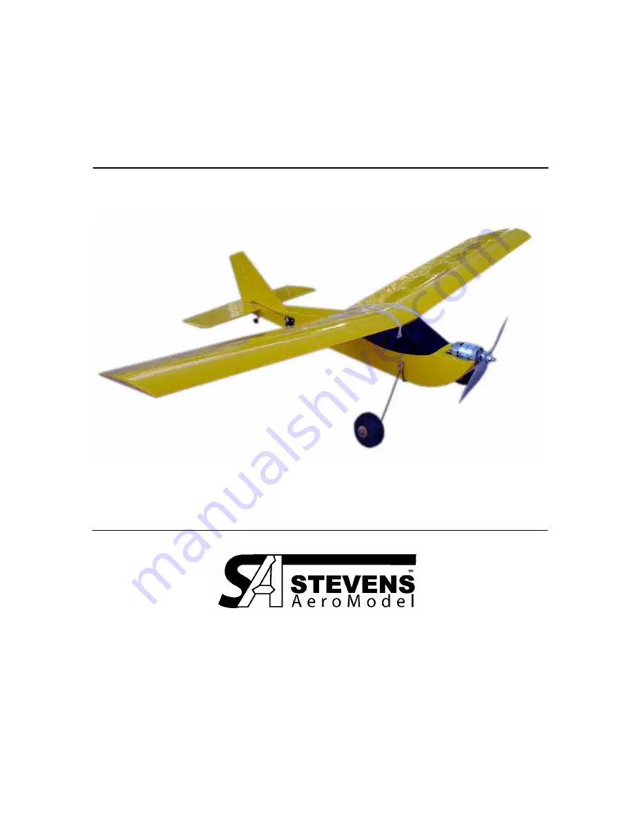
SQuiRT-700
A Speed 700 Primary Trainer
R1.01
Span 57” / Length 39” / Area 560 Sq.” / Flying Weight 40-48 oz.
© 2005 Stevens AeroModel all rights reserved.
Page 1: ...1 SQuiRT 700 A Speed 700 Primary Trainer R1 01 Span 57 Length 39 Area 560 Sq Flying Weight 40 48 oz 2005 Stevens AeroModel all rights reserved...
Page 2: ...nty without notice In that Stevens AeroModel has no control over the final assembly or material used for final assembly no liability shall be assumed nor accepted for any damage resulting from the use...
Page 3: ...ell on a 3 4 Channel Transmitter 2 Hitec HS 81 Servos use of HS 81 servos will negate the need for two 6 servo extensions 2 6 Servo Extension Only required if you do not use the suggested HS 81 Servos...
Page 4: ...aser Engineered Kits 4550 Beaumont Rd Colorado Springs CO 80916 Assembly Tips READ THE INSTRUCTIONS and the plan sheet prior to starting any work Tape plans to work table Cover with wax paper or plast...
Page 5: ...Edge Square Sanding Guide H and V Stabilizer 45 Deg Leading Edge Leave Trailing Edge Square Sanding Guide Rudder Elevator 4 Remove the Rudder and Elevator Parts and sand a 45 deg bevel to the leading...
Page 6: ...ts with FRONT facing the nose of the model Tip If a part does not fit properly check the forward orientation 3 Locate the 1 8 Lite Plywood part F1 and dry fit to the core as indicated in the photo bel...
Page 7: ...e rear of the core assembly and the fuselage sides as indicated in the photo below Once satisfied with the fit glue the fuselage side to the core assembly Repeat for the opposite side Tip you must fit...
Page 8: ...e fuselage on your work surface square and retain parts with thin CA glue 10 Locate the 1 16 Plywood servo tray and glue inside the fuselage as indicated in the photos below Next locate the 3 32 balsa...
Page 9: ...e Should you choose not to make the steerable tail gear assembly you may mount almost any tail gear to this ply re enforced area of the SQuiRT fuselage 12 Next fit the 1 8 balsa part F10 to the aft en...
Page 10: ...ch cross brace from 3 32 balsa parts C1 C2 and C3 as indicated in the photos below With the catch brace assembled install one 3 16 rare earth magnet in the circular cutout secure the magnet with thin...
Page 11: ...eversed Also make certain you install your magnet in the hole that matches the magnet installed within the fuselage assembly 18 Now locate the F14a F14b and F14c balsa sheeting and sheet the nose of t...
Page 12: ...he plan sheet These dowels must be secured with CA glue TIP Sand the edges of the dowel smooth to avoid damaging the rubber bands 3 Retain the supplied 3 Lite Wheels to the landing gear assembly using...
Page 13: ...u ll need to drill your APC 10x5e prop hub using a 5 16 drill to fit the propeller adapter Once you have reamed the prop hub to 5 16 install the appropriate sized precision adapter included with your...
Page 14: ...e Key the S1 spar assembly to one of the 1 16 Balsa W1 lower D LOC parts and lock the spar to W1 with each of the five R2 ribs Reference this photo and the plan sheet for placement Lay this half of th...
Page 15: ...e root Repeat for the opposite wing half 5 Locate the 3 32 part W5 and install to the center wing section W5 spans the lower center section of the wing keys into the spar and butts against the W1 part...
Page 16: ...as indicated in the following photo Once satisfied with the alignment glue into position with thin CA glue You ll now join the wing trailing edge TE1 to the outside edge of ribs R1 and TE2 as illustr...
Page 17: ...glue Reference the photos below for the lower cap strip placement 11 Locate the 3 32 balsa wing tip parts W3 Key W3 to the spar S1 and align the underside with the bottom of the outer rib R3 Once sat...
Page 18: ...to W1 this is IMPORTANT there will be a gap between the W1 and W2 sheets at the wing leading edge Do not try and pinch W2 down to adhere to W1 14 Next locate and install the 3 32 balsa W10 upper cap...
Page 19: ...center section to follow the dihedral in the wing Complete the leading edge by butting the remaining dowels flush to the center dowel and extending the leading edge out to the wing tip Trim away the e...
Page 20: ...o lock into position 2 Poke two small holes in the covering at each wing retention dowel point and at the install point for the 3 16 landing gear lug dowel Reference the plan sheet for more detail 3 H...
Page 21: ...difficult to fly at near stall speeds A model that always drops one wing at stall will often have a bit of twist in the wing or wash in on the wing that drops 5 Set control surface throws to the mech...