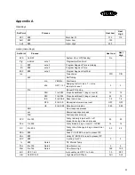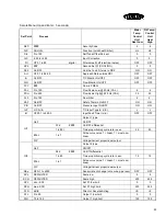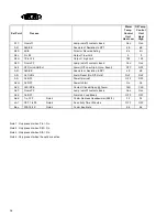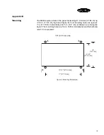
30
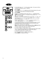
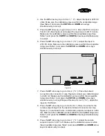
10. Press the UP arrow key to go to CAL 8 (“
)
))
)
”). The left display should
read between 5400 and 6400 (hexadecimal).
11. Press the UP arrow key to go to CAP 9 (“
$
$$
$)
))
)
”). Press the ENTER key.
The right display will blink. Observe the temperature from the Ambient
Temperature Indicator. Press the UP and DOWN arrow keys until you
reach the ambient temperature. Press the ENTER and DOWN arrow
keys to retain (display will blink to indicate value is accepted).
12. Press the UP arrow key to go to CAL A (“
)
))
)
”). Place load (1.5K ohm
resistor) into terminals 1 and 3 of connector K, see Figure-4. Connect
frequency generator and frequency counter across the load. Adjust the
input to 50 Hz (41 Hz for 75 GPM). Make sure the calibration value is
within the acceptable range (see Table 1) and press the ENTER and
DOWN arrow keys simultaneously to accept.
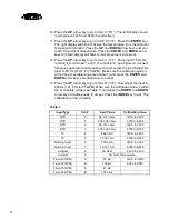
13. Press the UP arrow key to go to CAL B (“
)
))
)
”). Now adjust the input to
200 Hz (131.5 Hz for 75 GPM). Make sure the calibration value is within
the acceptable range (see Table 1) and press the ENTER and DOWN
arrow keys simultaneously to accept. Press the INDEX key to exit. The
calibration is now complete.
Table-1
Input Type
Cal. #
Input Value
Calibration Value
RTD
0
99.114 ohms
18CA to 22CF
RTD
1
2351.38 ohms
8759 to B228
RTD
2
99.114 ohms
18CA to 33CF
RTD
3
2351.38 ohms
8759 to B228
TC
4
4.663 mV
18CA to 22CF
TC
5
73.953 mV
8759 to B228
Remote Input
6
1.224 mA
18CA to 22CF
Remote Input
7
19.721 mA
8759 to B228
Ambient
8
Ambient
5400 to 6400
Ambient
9
Ambient Temperature
Flow (30 GPM)
A
50 Hz
18CA to 36D9
Flow (30 GPM)
B
200 Hz
6d48 to 9816
Flow (75 GPM)
A
41 Hz
Flow (75 GPM)
B
137.5 Hz
Summary of Contents for M2B
Page 1: ... Rev A ...
Page 49: ...48 ...

