29
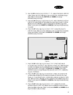
4. Use the UP arrow key to go to CAL 1 (“
"
""
")
))
)
”). Adjust the input to 2351.38
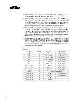
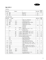
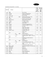
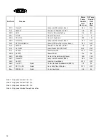
ohms. Make sure the calibration value is within the acceptable range
(See Table 1) and press the ENTER and DOWN arrow keys
simultaneously to accept.
5. Press the UP arrow key to go to CAL 2 (“
)
)
)
)
”). Move the RTD connector
from D to E (See Figure-4) and adjust the Input down to 99.114 ohms.
Make sure the calibration value is within the acceptable range (See
Table 1) and press the ENTER and DOWN arrow keys simultaneously
to accept.
6. Press the UP arrow key to go to CAL 3 (“
/
//
/)
))
)
”). Adjust the input to
2351.38 ohms. Make sure the calibration value is within the acceptable
range (see Table 1) and press the ENTER and DOWN arrow keys
simultaneously to accept.
Figure-4
7. Press the UP arrow key to go to CAL 4 (“
.
..
.)
))
)
”). Place the millivolt
connection into connector C (see Figure-4). Adjust your millivolt signal
to 4.663 mV. Make sure the calibration value is within the acceptable
range (see Table 1) and press the ENTER and DOWN arrow keys
simultaneously to accept. Repeat this step for Cal 5 (“
0)
0)
0)
0)
”), adjust the
input for 73.953mV.
8. Press the UP arrow key to go to Cal 6 (“
1)
1)
1)
1)
”). Place the wires for the
remote setpoint input into the last 2 terminals of connector A2. See
Figure-4. (+ to terminal 3 and - to terminal 4). Adjust your input to 1.224
mA. Make sure the calibration value is within the acceptable range (see
Table 1) and press the ENTER and DOWN arrow keys simultaneously
to accept.
9. Press the UP arrow key to go to CAL 7 (“
,
,,
,)
))
)
”). Adjust the remote
setpoint input to 19.721 mA. Make sure the calibration value is within
the acceptable range (see Table 1) and press ENTER and DOWN arrow
keys simultaneously to accept.
P7
P8
H
A2
C
D
E
K
A
Flow Input
RJC
Summary of Contents for M2B
Page 1: ... Rev A ...
Page 49: ...48 ...

