background image

Document # 82070-637, Revision D 

CONFIDENTIAL 

© 2009 Copyright VTS Medical Systems, LLC


23 of 29


Using Picture In Picture (PIP) and  

Picture And Picture (PAP) Modes 

These features are available only through the remote control. 

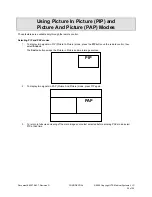
Selecting PIP and PAP modes 

1.  To display two signals in PIP (Picture In Picture) mode, press the 

PIP

 button on the remote control, then 

select 

S

OURCE

.  

The 

S

WITCH

 button swaps the Picture in Picture and main image sources. 


2.  To display two signals in PAP (Picture And Picture) mode, press PIP again.  


3.  To return to full screen viewing of the main image source last selected before entering PAP mode, select 

PIP a third time. 

PAP


PIP 

Summary of Contents for VividImage MON-STE42SDI-MD

Page 1: ...VividImage Medical Grade High Definition Wide Screen Monitor OPERATION MANUAL MON STE42SDI MD MON STE42SDI MT MON STE52SDI MD MON STE52SDI MT MON STE42SDI MD ...

Page 2: ...dard Equipment evaluated to this standard is not suitable for use in the presence of a flammable anesthetic mixture with air or with oxygen or nitrous oxide unless additional tests have been passed Therefore this device is not suitable for use in the presence of a flammable anesthetic mixture with air or with oxygen or nitrous oxide MON STE42SDI MD MON STE42SDI MT MON STE52SDI MD MON STE52SDI MT T...

Page 3: ...w 8 Configuring Touch Capability 8 Control Devices 9 Side Control Panel 9 Figure 5 The Side Control Panel Table 2 Side Control FunctionsRemote Control 9 Remote Control 10 Overview of Remote Control Functions 10 Figure 6 The Remote Control Table 3 Remote Control Functions 10 Changing the Remote Control Battery 10 Figure 7 Changing the Remote Control Battery 10 On Screen Display OSD 11 Navigating OS...

Page 4: ...usting Monitor Settings with Hot Key Controls 21 Input Source Selection 21 Figure 16 Input Source Selections 21 Mode Item Selection 22 Figure 17 Color Mode Selections 22 Gamma Item Selection 22 Figure 18 Gamma Value Selection 22 Using Picture In Picture PIP and Picture And Picture PAP Modes 23 Selecting PIP and PAP modes 23 Primary Source and Secondary Source Selection 24 Table 10 PIP and PIP Func...

Page 5: ...itor Location Use the monitor in a suitable environment See Operating Temperature and Storage Temperature on the Specifications page of this manual Use caution around liquids as you would with any electrical appliance Do not insert objects into the monitor Do not place the monitor on unstable surfaces In all cases refer to the specifications in this manual to ensure proper monitor performance Use ...

Page 6: ...cluded in the carton are the following items 1 VividImage HD Wide Screen Monitor 1 DVI cable 1 VGA cable 1 S Video Cable 1 Power Cable 1 Remote 8 Mounting Screws Attached to the monitor 1 Touch Setup CD MON STE42SDI MT MON STE52SDI MT only 1 Quick Start Guide 1 DVI Cable 1 VGA Cable 1 S Video Cable 1 Power Cord 1 Remote Control Figure 1 Included Cables If any one of these items is missing please c...

Page 7: ...igure 2 Mounting Holes Connecting the Video Inputs The video input cable s should be attached to the appropriately labeled ports on the back of the monitor as shown below The following inputs are available Name Connection Type VGA RGB input D Sub 15pin x1 DVI input DVI D x1 Y Cb Cr input 8pin Mini Din x1 S Video input 4pin Mini Din x1 Video Input RCA Jack x1 HD SDI input Option BNC Connector x3 RG...

Page 8: ...MT touch enabled monitors come preconfigured for use as a touch panel To use the touch capability a connection to the RS232 Serial Touch port or USB Touch Control port must be made to the system you wish to control with the touch panel If neither of these ports is used the monitor functions as a monitor only with no touch capability Should you ever need to reconfigure the touch panel the Crystal T...

Page 9: ...l panel consists of seven push buttons located on the side of the monitor The side control panel is shown in Figure 2 below Figure 5 The Side Control Panel Table 2 Side Control Functions No Button Description 1 Power On Off Green Normal Operation Orange No Signal Amber Power Saving Off Power Off 2 ENTER Activate Selection when in menu Input Source Selection when not in menu 3 Menu Right Value Incr...

Page 10: ...ng the Remote Control Battery 1 Push down and pull out battery compartment 2 Insert one new 3V lithium battery Make sure the polarity of the battery is correct 3 Close battery compartment No Button Description 1 POWER Power ON OFF 2 Menu Left 3 Menu Up 4 ENTER Enter a Selection or Advance to Next 5 AUTO Auto Adjust Clock Phase Horizontal and Vertical Position 6 PIP Select Picture in Picture Pictur...

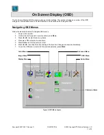
Page 11: ...SD Menus Follow the instructions below to navigate OSD menus 1 Power on the monitor 2 On the side control panel or remote control press MENU 3 Press or to select main menu items 4 Press or to select sub menu items 5 Press ENTER to enter the sub menu item 6 Press or to modify the current setting of the function Changes are saved automatically 7 To exit the OSD menu or return to the previous selecti...

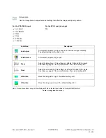
Page 12: ...rightness Adjusts the screen brightness See Glossary page 27 for more information The default setting is 64 Contrast Adjusts the image contrast See Glossary page 27 for more information The default setting is 50 Hue Adjusts the clarity and depth of the red blue and green colors See Glossary page 27 for more information The default settings for all three colors is 255 Saturation Adjusts the color s...

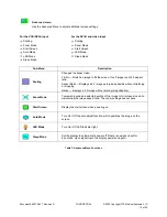
Page 13: ...ault setting for this field is On Auto Balance Automatically adjusts image color Phase Adjust the image focus This setting only affects VGA and DVI A inputs See Glossary page 27 for more information The default setting is 0 Clock Adjust the clock setting This setting only affects VGA and DVI A inputs See Glossary page 27 for more information The default setting is 50 H Position Move the image left...

Page 14: ... default setting is 2 2 Color Temp Change the color temperature Selections are 6500K 7500K 8200K 9300K Natural User The default setting is 9300K User Color Adjust red green blue gain This setting is available only when the Color Temp is set to User The default setting for all colors is 255 Black Level Adjust the black level of the screen This function will affect only the video source selected It ...

Page 15: ... ratio Aspect Ratio Displays a 4 3 image as large as possible without stretching or cropping Native displays a 4 3 image without scaling magnification Zoom Mode Temporarily expand a selected portion of the image to full screen size while maintaining the image aspect ratio The zoom setting does not save Start Screen Display the start screen when powering on Auto Mode Turn On Off the auto adjust fun...

Page 16: ...on Rotation Time Out Language H Position V Position Rotation Time Out Language Sub Menu Description H Position Moves the OSD menu left and right V Position Moves the OSD menu up and down Rotation Rotates the OSD menu Time Out Adjusts the amount of time the OSD displays Language Choose language to be used in screen menus Select ions are English Chinese French German Italian Spanish The default is E...

Page 17: ...actory settings Lock Mode Lock and unlock the OSD functions DVI Select Select DVI D or DVI A source Information Display firmware version source and resolution ID Choose the desired monitor ID connected to an external control device by the RS 232 IN port The adjustment range of monitor ID is 1 250 Note The RS 232 IN port can be used to connect an external control device such as a computer to contro...

Page 18: ... 2009 Copyright VTS Medical Systems LLC 18 of 29 Locking the OSD To Lock the OSD 1 Press MENU 2 Select Setup Menu Figure 9 Setup Menu 3 Press to select the sub menu items Select LOCK MODE and press ENTER Figure 10 Setup Menu Lock Mode Selected ...

Page 19: ...n keys are unlocked press MENU to use OSD Mode 1 All function keys except Power are locked Mode 2 All function keys are locked except Brightness control and Power Press MENU to use the brightness control menu Figure 11 Setup Menu Lock Mode Selections 5 Press MENU to exit the OSD menu When Lock Mode is set to OFF pressing Menu causes the following menu to appear Figure 12 Display Menu ID ...

Page 20: ...emporarily Overriding the OSD Lock To temporarily override the lock setting when the Lock field is set to Mode 1 or Mode 2 Hold the key the button on back of the monitor until the message OSD unlocked displays on screen The OSD unlocks for 15 minutes then reverts to its previous setting Figure 15 OSD Unlocked Note If you temporarily override the Mode 1 or Mode 2 Lock setting as detailed in the sec...

Page 21: ...s Enter On the remote control press Source Figure 16 Input Source Selections VGA Acquire analog signal from the D sub 15pin input DVI A Acquire analog signal from the DVI input or RGBSync input DVI D Acquire digital signal from the DVI input Composite Acquire analog signal from the composite input S Video Acquire analog signal from the S Video input Component Acquire analog signal from the Y Cb Cr...

Page 22: ...display operation DICOM Mode DICOM standard operation CL Mode Clear base mode BL Mode Blue base mode LB Mode Light box mode for viewing X rays Gamma Item Selection To select a Gamma value on the remote control or side menu control panel press right Figure 18 Gamma Value Selection Native Disables the gamma function Gamma 1 8 1 8 gamma value Gamma 2 0 2 0 gamma value Gamma 2 2 2 2 gamma value DICOM ...

Page 23: ...electing PIP and PAP modes 1 To display two signals in PIP Picture In Picture mode press the PIP button on the remote control then select SOURCE The SWITCH button swaps the Picture in Picture and main image sources 2 To display two signals in PAP Picture And Picture mode press PIP again 3 To return to full screen viewing of the main image source last selected before entering PAP mode select PIP a ...

Page 24: ...the availability of PIP and PAP functions according to the primary source signal type Secondary Source VGA DVI A DVI D Composite S Video Component HD SDI 1 HD SDI 2 Primary Source VGA DVI A DVI D Composite S Video Component HD SDI 1 HD SDI 2 Key PIP function enabled PIP function disabled Table 10 PIP and PIP Function Availability for Signal Type Combinations ...

Page 25: ...s the power cord connected properly Are the power cord and AC outlet functional Are the computer and or video source s connected to the monitor properly Are the computer and or video source s turned on Is the main power switch on the back of the monitor turned on Has an input video signal been chosen see Input Signal Selection on page 13 of this manual that correlates to the video input s on the m...

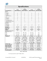
Page 26: ... C22 2 No 601 1 VCCI PSE BSMI CCC RoHS WEEE FCC Compliance CE Medical Device Directive Canadian ICES 003 CB IEC 60950 1 IEC 60601 1 UL 60950 1 CAN CSA C22 2 No 601 1 VCCI PSE BSMI CCC RoHS WEEE FCC Compliance CE Medical Device Directive Canadian ICES 003 CB IEC 60950 1 IEC 60601 1 UL 60950 1 60601 1 CAN CSA C22 2 No 601 1 VCCI PSE BSMI CCC RoHS WEEE FCC Compliance CE Medical Device Directive Canad...

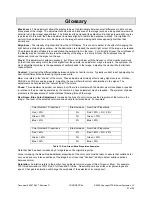
Page 27: ...ariations of similar colors Typically contrast is set by adjusting for best color differentiation between light yellow and white Hue Hue refers to the shade of the colors These adjustments primarily affect analog signal sources S Video RGBHV and VGA are analog signals Adjusting the hue will help to correct abnormalities in the signal The adjustment can help restore the natural look of the colors P...

Page 28: ...irmware Version 17 G Gain See Color Temperature Gamma 14 Gamma Value Selection 22 Glossary 27 H Horizontal Position 13 Hue 12 27 L LED On Off 15 M Monitor Care 25 Mounting 7 O On Screen Display 11 OSD 11 25 Menu Functions 12 Navigation 11 OSD Menu Language 16 Lock 18 Settings 16 Time Out 16 P Phase 13 27 Picture Position 13 Picture And Picture PAP 23 Picture In Picture PIP 23 Power 6 Power Cord 8 ...

Page 29: ...637 Revision D CONFIDENTIAL 2009 Copyright VTS Medical Systems LLC 29 of 29 Contact Customer Support 40 Melville Park Road Melville NY 11747 877 887 1788 VividImage is a registered trademark of VTS Medical Systems LLC ...

Reviews: