


23
2112 116TH AVE NE SUITE 1-5, BELLEVUE WA, 98004
WWW.STEPPIR.COM
TEL: (425)-453-1910 FAX: (425)-462-4415
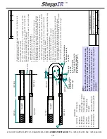
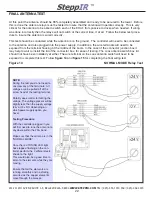
Figure 15
180 Mode Relay Test
NOTE:
During the test you do not need to
unscrew any of the terminals. All volt-
ages can be pulled off of the screw
head of the testing terminal.
Polarity does not matter for testing the
voltage. It does not matter if you use
the positive or common probe of the
volt meter.
Testing Procedure:
With the antenna still in the 20M band
press the “180” button on the con-
troller. Make sure the LED light next to
the 180 button is lit.
Once the red TUNING LED light has
stopped flashing on the controller.
Perform the 3 different tests shown to
the right.
If all the voltages were correct from all
six tests, press the RETRACT button
to send the elements to the home
position.
Once the red TUNING LED light has
stopped flashing and the controller
power is off, unplug the power and
control cables from the controller.
If not all the voltages were correct
refer back to the wiring diagram and
double check to make sure all wires
are in the correct location.
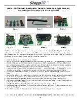
Once the correct voltages have been tested assembly can now be completed by securing the termi-
nal blocks and wiring inside the terminal housing
figure 8
. Also the lid of the Coax Antenna Switch
can now be secured along with the gasket shown in
figure 4.
+
-


