


2112 116TH AVE NE SUITE 1-5, BELLEVUE WA, 98004
WWW.STEPPIR.COM
TEL: (425)-453-1910 FAX: (425)-462-4415
12
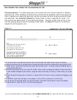
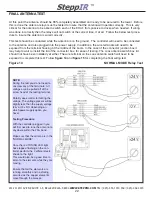
WIRING THE COAX CABLE TO THE ANTENNA SWITCH
The coax cables have been made specifically for each individual element.
Follow
figure 7
and
figure 8
below for connecting the coax to the antenna switch box.
Tighten all coax connectors with pliers to ensure a good connection.
Weather-proofing should be done when all testing and assembly have been completed.
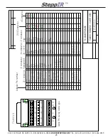
Figure 7
Wiring Coax to Elements
REFLECTOR
DRIVEN
DIRECTOR
DB11
Coax Antenna Switch
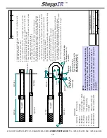
Figure 8
Wiring Coax Antenna Switch
For details on wiring the Coax Antenna
Switch refer to
Figure 7
below. The lid
of the Coax Antenna Switch should not
be attached yet.
Reflector EHU
Feed from shack
Control cable that will be
wired into the terminal
housing or connector box.
Driven EHU
Director EHU
Bottom View of Coax Antenna Switch
Notes:
Take care not to bend the cable over any sharp corners of the boom assembly, or particu-
larly, the top plate on the antenna tower, or the cable could be damaged. Do not bend the cable in a
smaller diameter than 10 inches. Do not clamp anything over the cable that could possibly pinch, or
damage it. A short-circuit of the cable may cause damage to the electronic controller.
OUT 2
OUT 1
OUT 3


