STEPCRAFT Touch-Probe Operating And Safety Instructions Manual Download Page 13

13 


Using the Touch Probe to 3D scan an object 


Another use of the Stepcraft Touch Probe is scanning the surface of an object to obtain a 3D Point Cloud that can 
make a 3D representation of the object for milling, 3D printing, or for redesign it. 

The scanning process uses the UCCNC plugin AutolevelerCA capabilities to make a matrix of scan coordinates 
that will enclose the object in a 3D virtual box from which will obtain each of the matrix points as 3D coordinate 
points. 

One thing to have in mind is that the scan is made based on the Z height of each scanning point, so details of an 
object that are hidden below rigs or “bridges” can’t be obtain with this method. 


Before starting any scanning procedure make sure that the probe is working properly and is 
adjusted to the correct tension, working with a untested Touch Probe can cause damage to the 
probe or personal injuries 


CLAMPING AND MEASURING YOUR OBJECT 

Clamp your object on the Stepcraft working table taking care that the clamping won’t interfere with the scanning 
area or the probe movement on all axis, if you object has a flat surface it can be fixed with double-sided tape or 
painters tape as long as it does not interfere with your scanned area and the object is completely secured on the 
table. 

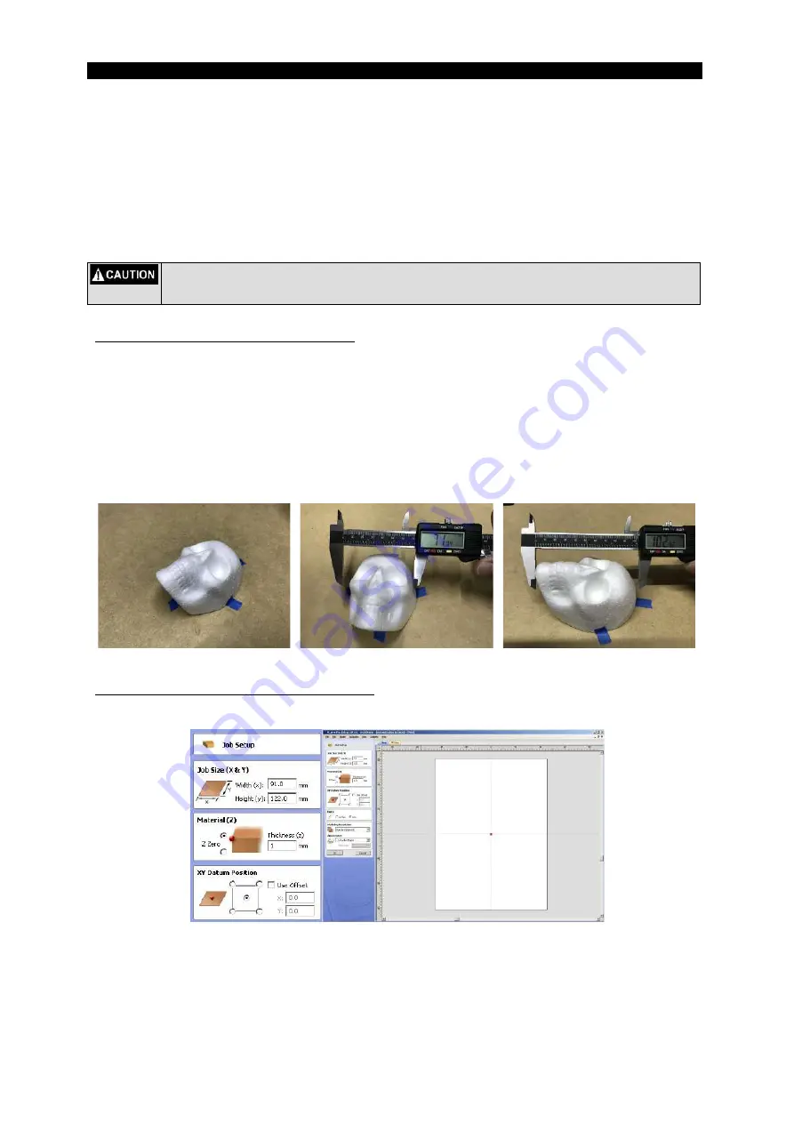
Measure the width (X-axis) and length (Y-axis) of the object. If the object has an irregular shape, you need to take 
measurements using a ruler or caliper (shown below), as if the object is inside a box. Write down these 
measurements as they are going to be used to find the center of the object to begin the scanning. 


MAKING THE OBJECT ENCLOSURE TOOL PATH 


Open your Vectric software, add 20mm to the width and length of your object and make a new project with these 
values selecting the XY datum position in the center and set the material thickness to 1mm. 


Summary of Contents for Touch-Probe

Page 1: ...medication A moment of inattention while operating the Stepcraft CNC may result in serious personal injury NOTICE All persons who operate the Touch Probe must have read and fully understood all relevant operating instructions Misunderstandings may result in damage to the device or personal injury NOTICE Dress properly Do not wear loose clothing or jewelry Keep your hair clothing and gloves away fr...

Page 2: ...her practical way and secure way to support and attach the workpiece to the machine table Holding the workpiece with your hands leaves it unstable and may lead to loss of control Parts and functions of the Touch Probe 1 Body 2 Cable to be connected to Stepcraft circuit board 3 Collet 4 Stylus 5 XYZ Sensitivity Adjustment Screws 6 Mounting Post 8mm 7 Tension Adjustment Screw Touch Probe Uses The To...

Page 3: ... more than 10 minutes and the only tool required is a 2mm Allen Wrench and a small flat head screwdriver INSTALLING THE WIRE TO THE STEPCRAFT CIRCUIT BOARD STEP 1 Turn the machine on its side and remove the two screws that secure the bottom board cover using a 2mm Allen Wrench One screw should be securing the green ground wire to the bottom of the machine STEP 2 Remove the circuit board cover and ...

Page 4: ...to 20mm Proxxon Tool Adapter P 10107 19 99 or you can use an 8mm collet in your spindle and mount it like you would an end mill USING TOOL ADAPTERS STEP 1 Gather than Touch Probe 20mm to 8mm Tool Adapter and 43mm to 20mm Proxxon Tool Adapter STEP 2 Insert the 20mm to 8mm Tool Adapter into the 43mm to 20mm Proxxon Tool Adapter making sure that the slots in each adapter line up NOTE It will look lik...

Page 5: ...h Probe or personal injury Installing the Screen Set and Macros into UCCNC In order to use the Screen Set and Macros for the Touch Probe you must have the latest version of UCCNC installed which is at least V 1 2026 Visit www stepcraft us touchprobe and click on the DOWNLOADS tab There you will find the Screen Set Files for the Touch Probe as well as the latest version of UCCNC There are four Scre...

Page 6: ...hen press the Next button to continue Make sure Create desktop icon is checked and then click Next to proceed Click Finish on this screen to complete the installation On your Desktop you should see a new Icon labeled SC2 300 3D Probe NOTE the 300 will be replaced with your machine size RUNNING UCCNC WITH THE TOUCH PROBE SCREEN SET Click the new icon labeled SC2 XXX 3D Probe XXX your machine model ...

Page 7: ...ved surface and 3D scanning of objects Below we will show you how to use each of these functions LOCATING THE CENTER OF THE INSIDE OF A CIRCLE SQUARE OR RECTANGLE The Touch Probe can be used to automatically find the center of the inside of a circle square or rectangle CIRCLE To locate the center of a circle be sure to place the touch probe in the center area of the circle You will need to measure...

Page 8: ...ving operation as the X and Y zero positions are now set NOTE You will need to set your Z zero when you switch to a spindle with an end mill SQUARE RECTANGLE To locate the center of a square or rectangle be sure to place the touch probe in the center area of the square rectangle You will need to measure the width and length in mm of the square rectangle Be sure that the tip of the probe is NOT tou...

Page 9: ... Press OK to close the window At this point you can simply replace the touch probe with a spindle and begin your milling cutting carving operation as the X and Y zero positions are set NOTE You will need to set your Z zero when you switch to a spindle with an end mill LOCATING THE CENTER OF A CIRCLE SQUARE OR RECTANGLE FROM THE OUTSIDE The Touch Probe can be used to automatically find the center o...

Page 10: ...e exact diameter of the circle Press OK to close the window At this point you can simply replace the touch probe with a spindle and begin your milling cutting carving operation as the X and Y zero positions are set NOTE You will need to set your Z zero when you switch to a spindle with an end mill SQUARE RECTANGLE To locate the center of a square or rectangle be sure to place the touch probe in th...

Page 11: ... bottom edge of the outer square rectangle followed by the top edge left edge and finally the right edge Each time the Touch Probe moves the Z axis raises 20mm to clear the object as it passes over to move to the next position When the macro is finished running the Z axis will raise one more time and the X and Y axis will move the touch probe will end in the EXACT center position of the square rec...

Page 12: ...t with a square corner using the following buttons To use them place the touch probe about 1 8 3mm inside the corner on the object that you wish to probe with the probe about 1 8 3mm above the object Z axis Follow the prompts on the screen once you click the button Locate the top left corner of an object Locate the top right corner of an object Locate the bottom left corner of an object Locate the...

Page 13: ... untested Touch Probe can cause damage to the probe or personal injuries CLAMPING AND MEASURING YOUR OBJECT Clamp your object on the Stepcraft working table taking care that the clamping won t interfere with the scanning area or the probe movement on all axis if you object has a flat surface it can be fixed with double sided tape or painters tape as long as it does not interfere with your scanned ...

Page 14: ...ts It will scan everything inside the box After calculating the tool path save the file to your computer s desktop or in a location that will be easy to find Not setting the spindle speed to zero can cause severe damage to the Touch Probe or personal injury SETTING THE TOUCH PROBE POSITION FOR SCANNING Mount the Touch Probe on the machine with one of the methods described previously Open UCCNC wit...

Page 15: ... axis approx 10mm up then move the Touch Probe close to the X and Y zero coordinates From this position move the Touch Probe half of the width of your object on the X axis and half of the length Y Axis and set to Zero both axis X and Y only do not Zero the Z axis This is the center of your object You are ready to scan Make sure that the Z zero value was probed on the highest part of your scanned o...

Page 16: ...onger it will take to complete the scan Z Feed This is the feed rate value for probing on the Z axis A good value range is between 150 to 400 A lower value will increase accuracy but will increase scan time Manual Zero Auto Zero Select Manual Zero we already set the Z zero on the highest part of our object Create GCode and send to UCCNC button Once you set the desired values for the different opti...

Page 17: ...ST BE TURNED OFF to prevent the spindle from starting which can cause severe damage to the Touch Probe or personal injury After the scanning procedure ends the machine will stop press the DIGITIZE OFF button and a file popup will appear Select a location to save your point cloud and press SAVE Finally press CYCLE STOP and you have finished the scanning process Converting the 3D Point Cloud to STL ...

Page 18: ...our object on the screen Under the Render menu select Show Normal Curvature option this will show the Normals from each of the points Adjust the Normals of the Points under the menu Filters Normals Curvatures and Orientation Compute normal for point sets press APPLY with the default options and then Close You will get all the Normals from the point cloud aligned along the object To make the polygo...

Page 19: ...reas press the Arrow Up button in the perc on 0 124 603 option and press APPLY again and repeat this procedure until you reach good polygon coverage Sometimes your object will have some holes in it which we will show you how to close in the next step NOTE You can interactively rotate your object by pressing the mouse button on top of your object and moving your mouse to get a better view of the de...

Page 20: ...ularities are on the surface so please keep this in mind if you are planning to avoid distortions on logo or text engraving NOTE All the values showed here are just used as an example your own settings and values will vary according to your work Before starting any scanning procedure make sure that the probe is working properly and is adjusted to the correct tension working with a untested Touch P...

Page 21: ...ing the end mill as you normally do and save your tool path to your hard drive SETING UP THE TOUCH PROBE POSITION FOR SCANNING Mount the Touch Probe on the machine with one of the methods described before Open UCCNC with the SC2 XXX 3D Probe profile already installed on your machine should be on your desktop Minimize or send to the back the AutolevelerCA plugin window touching the UCCNC window Mov...

Page 22: ...eeded to set the end mill offset in the correct Z height position in the next step Load your engraving tool path to UCCNC and bring back the AutolevelerCA plugin You will see that your toolpath is shown on the plugin window The settings to change on the AutolevelerCA plugin are as follows Probe Clearance Distance in mm to move the probe up from the Z zero point safe distance from your object use a...

Page 23: ...s the button CYCLE START to start the Scan Process the machine will move and start scanning one point at a time NOTE If you press CYCLE STOP in any moment of the scanning procedure or after its finished you will lose the scanning values already made and you need to start all over again After the scanning procedure ends the machine will stop proceed to obtaining the offset value between the end mil...

Page 24: ... Bed by this logic the Touch Probe is closest to the bed than the endmill means that its longer to set the endmill to the same height as the Touch Probe we need to move the endmill by 1 47mm down In this case to obtain the same Material Zero for the endmill we need to lower the endmill 1 47 so the new Zero Point in machine coordinates for the endmill will be 24 77 1 47 26 24mm Move the endmill to ...

Page 25: ...offset procedure or after its finished you will lose the scanning values already made and you need to start all over again After the engraving is finished the machine will stop now you have sucessfuly achieve engraving a Tool path on an irregular surface ...

Reviews: