WWW.STEMMER-IMAGING.COM
PP500 LED lighting controllers - User Manual
10
Reference information
10.1 Timings
Switched mode:
The maximum delay from a trigger input changing to the
output current being turned on or off is 10μs.
Pulse Mode:
For the PP500F the minimum pulse delay is about 4μs.
10.2 Specifications
Parameter
Value
Notes
Digital supply voltage
(PSU+)
12 - 48VDC
regulated
Must be at least 1V greater than the load
potential difference at maximum current.
Quiescent current
150mA
This is when using a 12V supply; the
current is lower at 24V.
Input enable level
From 3V to 24V
This is the voltage applied between
+ and − of each input.
Input disable level
< 1V
See above.
Typical trigger input
current
3mA at 3V to
24V
Max output current per
channel
2A continuous,
10A pulsed
Maximum total average
output current
2A
The average current for all channels
added together must not exceed this.
Ambient temperature
during operation
5°C to 40°C
The ambient temperature may need to be
lower if the PP500 is dissipating a lot of
heat.
Total allowed power
dissipation without heat
sinking (P
D
)
8W maximum
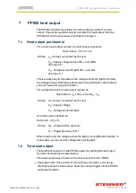
See Section 7, PP500 heat output.
Pulse timing
20μs to 1s
1μs to 1s
PP500
PP500F
Delay timing
20μs to 1s
4μs to 1s
PP500
PP500F
—
30
—
WWW.STEMMER-IMAGING.COM


