


3/96
5 - 3
09-282C
SERVICE
section 5
MAINTENANCE AND ADJUSTMENTS
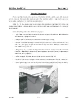
Before inspecting or servicing any part of the
machine, disengage PTO and make sure all
moving parts have come to a complete stop.
The chipping knives and shredding sections are
sharp! Use care when working on machine to
avoid injury.
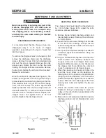
SHREDDER SECTIONS
The serrated self sharpening shredder sections
are designed to offer long life and can be
reversed if they become dull. To remove or
replace the sections, proceed as follows:
A. Remove discharge shield, discharge screen and
knife access cover.
B. Work with one section shaft at a time. Remove
the #10-24 bolt from the section shaft. The shaft
can be removed through the access hole.
C. Remove sections and section spacers. Be
careful to keep track of the order the spacers
were installed on the shafts so they can be
returned to the original locations. If the spacers
are not installed properly, the rotor will be out of
balance and also will not have proper
shredding action.
D. Reverse or replace sections and reassemble
into the rotor. Reinstall #10-24 bolt and locknut
through spacer and torque to 36 inch pounds.
E. Complete service of all 6 shafts and replace the
knife access cover, discharge screen and
discharge shield.
CLEANING PLUGGED ROTOR
If too large of material or too much material is fed
into
the
chipper/shredder,
it
may
become
plugged. To clear plugged rotor, proceed as
follows:
A. Disengage PTO and stop engine.
B. Remove discharge shield and discharge screen.
C. Clean debris out of the shredding rotor. Turn the
rotor by hand to be sure it is free to rotate.
D. Replace discharge screen and discharge shield.
E. See also Cleaning Plugged Blower.
BELT REPLACEMENT
Check the condition of the double drive belts
every
30
hours
of
operation
or
annually,
whichever occurs first. Only replace belts in sets.
To replace belts proceed as follows:
A. Disengage PTO and stop engine.
B. Remove belt shields.
C. Remove belt idler spring and remove belts from
pulleys.
D. Remove 4 bolts attaching hitch assembly to
main frame and completely remove belts.
E. Place new belts around the hitch frame and
attach the hitch assembly to the main frame.
F. Position belts on the pulleys and attach the idler
arm spring.
G. Check the attachment drive belt and replace if
needed. Replace belt shields.
CLEANING PLUGGED BLOWER
If too much green material is fed into the
chipper/shredder
the
blower
may
become
plugged. To clear the blower, proceed as follows:
A. Disengage PTO and stop engine.
B. Remove blower drive belt guard, and remove
drive belt.
C. Remove the Blower discharge tube.
D. Tilt the blower away from the main frame and
clean debris out of blower housing.
Summary of Contents for CS312
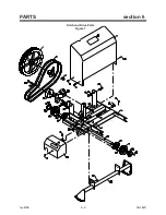
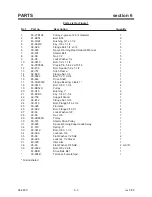
Page 16: ...rev 8 98 6 2 09 282C PARTS section 6 Hitch and Drive Parts Figure 1 ...
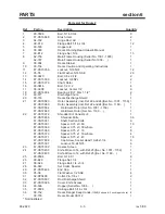
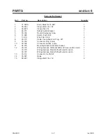
Page 18: ...rev 5 00 6 4 09 282C PARTS section 6 Frame Parts Figure 2 ...
Page 20: ...rev 8 98 6 6 09 282C PARTS section 6 Emergency Stop Switch Parts Figure 3 ...
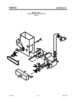
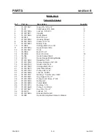
Page 22: ...rev 5 00 6 8 09 282C PARTS section 6 MODEL CS313 Chipper Shredder Blower Parts Figure 4 ...
Page 30: ......