09-282C
5 - 2
3/96
SERVICE
section 5
MAINTENANCE AND ADJUSTMENTS
Before inspecting or servicing any part of the
machine, disengage PTO and make sure all
moving parts have come to a complete stop.
The chipping knives and shredding sections
are sharp! Use care when working on machine
to avoid injury.
SHARPENING CHIPPER KNIVES
It is recommended that the chipper knives are
sharpened every 5 to 15 hours of chipper
operation, depending on the type of wood fed
into the chipper.
To remove the chipper knives for sharpening, first
remove the discharge shield and the discharge
screen. Remove the two 5/16 inch retaining bolts
and pull the screen outward. Remove the knife
access cover. Rotate the rotor so that the bolts
holding the chipper knife are accessible. Remove
the two bolts holding the knife and the knife itself.
Repeat for all 4 knives.
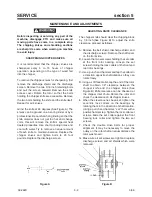
Grind the knife at 45 degrees.(See Figure A) The
knives can be ground on a bench grinder or by a
professional. Be careful when grinding so that the
knife material does not get too hot and change
color, this will remove the knife's special heat
treated properties. Use short grinding times and
cool with water. Try to remove an equal amount
off each knife to maintain balance. Replace the
chipper knives and tighten bolts to 20 foot
pounds. Replace the discharge screen.
ADJUSTING KNIFE CLEARANCE
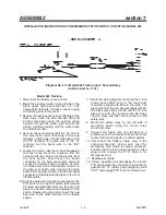
The chipper knife should clear the chipping block
by 1/8 inch.(See Figure B) To adjust the knife
clearance, proceed as follows:
A. Remove the belt shield, discharge shield, and
the discharge screen. Remove the shaft cover
on the front side.
B. Loosen the two set screws holding the set collar
at the front rotor bearing. Loosen the set
screws holding the lock collars on the front and
rear rotor bearings.
C. Use a punch and hammer and tap the collars in
a direction opposite shaft rotation so they can
rotate freely.
D. Using a soft face mallet, tap the end of the rotor
shaft to obtain 1/8" clearance between the
chipper knife and the chipper block.(See
Figure B) Knife clearance can be checked at
the chipper inlet chute. Rotate the rotor and
check the clearance on all chipper knives.
E. When the clearance has been set, tighten the
eccentric lock collars on the bearings by
rotating them in the direction of shaft rotation.
Using a punch and hammer, “set” them with a
positive hammer tap. Tighten the lock collar set
screws. Slide the set collar against the front
bearing lock collar and tighten the two set
screws.
F. Check the double drive belts for proper
alignment. It may be necessary to move the
pulley on the rotor shaft an equal distance the
rotor was moved.
G. Make sure all set screws are tight and replace
discharge screen and all shields which were
removed.
Figure A
Figure B
Summary of Contents for CS312
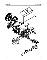
Page 16: ...rev 8 98 6 2 09 282C PARTS section 6 Hitch and Drive Parts Figure 1 ...
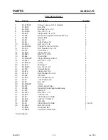
Page 18: ...rev 5 00 6 4 09 282C PARTS section 6 Frame Parts Figure 2 ...
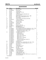
Page 20: ...rev 8 98 6 6 09 282C PARTS section 6 Emergency Stop Switch Parts Figure 3 ...
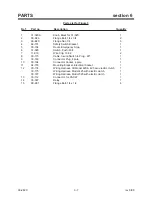
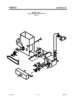
Page 22: ...rev 5 00 6 8 09 282C PARTS section 6 MODEL CS313 Chipper Shredder Blower Parts Figure 4 ...
Page 30: ......


