16
ZTM 1250
ZTM 1250
ZTM 1250
ZTM 1250
ZTM 1250
ADJUSTMENTS
HYDROSTAT ADJUSTMENTS
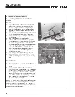
A turnbuckle-style hydrostat neutral adjustment is
provided.
Neutral:
1. Support the machine with the drive wheels off the
ground. Use jackstands or equivalent support.
Do not rely only on mechanical or hydraulic jacks.
2. Move the traction levers into the neutral position
and raise the seat and grass collection hopper or
utility box.
3. Disconnect the seat switch and temporarily connect
the two terminals with jumper wire
J
as shown.
4. Loosen jam nuts
T
( (h) =hidden) at both ends of
the turnbuckle.
5. Start the engine and run at low speed.
6. Hold one of the traction control levers up against
the resistance of the reverse return spring. Rotate
the corresponding turnbuckle until the wheel it
controls turns in reverse, then rotate the turnbuckle
in the opposite direction until the wheel stops
turning. Lock the turnbuckle jam nuts. Run the
engine up to high idle and stroke the pump in
forward and reverse to check the adjustment.
Re-adjust if necessary.
7. Repeat steps 4 through 6 for the opposite side.
8. Remove the jumper wire and reconnect the seat
switch. Lower the grass collection hopper or utility
box
Reverse Return:
1. Move traction levers to neutral and raise the seat.
2. Locknuts
U
should be run on the bolt as far as they
will go.
3. Loosen jam nuts
Y
. Move the traction levers to
their forward stop. Adjust the clevis yoke by turning
the head of the bolt until the pin through the clevis
yoke is up against the back end of the slot in the
traction control shaft lever. Once the initial setting
is made for both sides, the levers may be evened
up by adjusting the how far the bolt is turned into
the clevis. Tighten jam nut
Y
.
NOTE:
A slight creep in reverse is acceptable provided
the wheel does not turn and the hydrostat pump does
not whine when the parking brake is on. The reverse
return should be adjusted and set before neutral is set
on the hydrostatic transmissions.
Summary of Contents for 442105
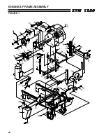
Page 26: ...24 ZTM 1250 ZTM 1250 ZTM 1250 ZTM 1250 ZTM 1250 ENGINE FRAME ASSEMBLY FIGURE 1 ...
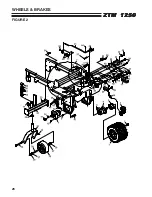
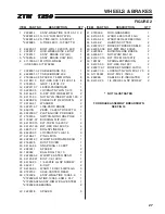
Page 28: ...26 ZTM 1250 ZTM 1250 ZTM 1250 ZTM 1250 ZTM 1250 WHEELS BRAKES FIGURE 2 ...
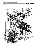
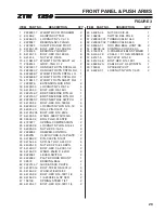
Page 30: ...28 ZTM 1250 ZTM 1250 ZTM 1250 ZTM 1250 ZTM 1250 FRONT PANEL PUSH ARMS FIGURE 3 ...
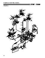
Page 32: ...30 ZTM 1250 ZTM 1250 ZTM 1250 ZTM 1250 ZTM 1250 PUMPS CONTROL PANEL FIGURE 4 ...
Page 34: ...32 ZTM 1250 ZTM 1250 ZTM 1250 ZTM 1250 ZTM 1250 BLOWER FUEL TANK FIGURE 5 ...
Page 36: ...34 ZTM 1250 ZTM 1250 ZTM 1250 ZTM 1250 ZTM 1250 BELTS FIGURE 6 ...
Page 38: ...36 ZTM 1250 ZTM 1250 ZTM 1250 ZTM 1250 ZTM 1250 BUMPER GRASSBOX FRAME FIGURE 7 ...
Page 40: ...38 ZTM 1250 ZTM 1250 ZTM 1250 ZTM 1250 ZTM 1250 HEAVY DUTY AIR CLEANER FIGURE 8 ...
Page 42: ...40 ZTM 1250 ZTM 1250 ZTM 1250 ZTM 1250 ZTM 1250 GRASSBOX FIGURE 9 ...
Page 44: ...42 ZTM 1250 ZTM 1250 ZTM 1250 ZTM 1250 ZTM 1250 ELECTRICAL FIGURE 10 ...
Page 46: ...44 ZTM 1250 ZTM 1250 ZTM 1250 ZTM 1250 ZTM 1250 HYDRAULICS FIGURE 11 ...
Page 48: ...46 ZTM 1250 ZTM 1250 ZTM 1250 ZTM 1250 ZTM 1250 SEAT ASSEMBLY FIGURE 12 ...
Page 50: ...48 ZTM 1250 ZTM 1250 ZTM 1250 ZTM 1250 ZTM 1250 DECALS FIGURE 13 ...
Page 52: ...50 ZTM 1250 ZTM 1250 ZTM 1250 ZTM 1250 ZTM 1250 OPTIONAL FILL INDICATOR 970145 FIGURE 14 ...
Page 54: ...52 ZTM 1250 ZTM 1250 ZTM 1250 ZTM 1250 ZTM 1250 HYDROGEAR PUMP FIGURE 15 ...
Page 56: ...54 ZTM 1250 ZTM 1250 ZTM 1250 ZTM 1250 ZTM 1250 BRAKE ASSEMBLY FIGURE 16 ...


