background image

32

ZTM  1250

ZTM  1250

ZTM  1250

ZTM  1250

ZTM  1250

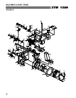
BLOWER & FUEL TANK

FIGURE 5

Summary of Contents for 442105

Page 1: ...dangers and should read the entire manual before attempting to set up operate adjust or service the machine SETUP PARTS MAINTENANCE MANUAL ZTM 1250 Power Unit Model 442105 Power Unit ZTM1250 25 Klr Collection Operation Safety Manual 4136742 For Cutterdecks 954204A Cutterdeck 42 Collection 954804A Cutterdeck 48 Collection Parts Manual 4136039 4136743 REV B ...

Page 2: ...tado de California hace saber que los gases de escape de los motores diesel y algunos de sus componentes producen cáncer defectos de nacimiento y otros daños en el proceso de reproducción humana L émission du moteur de ce matériel contient des produits chimiques que l Etat de Californie considère être cancérigènes provoquer des défauts congénitaux et d autres dangers en matière de reproduction El ...

Page 3: ...r any service or parts needed Steiner service ensures that you continue to receive the best results possible from Steiner s products You can trust Steiner replacement parts because they are manufactured with the same high precision and quality as the original parts Steiner designs and builds its equipment to serve many years in a safe and productive manner For longest life use this machine only as...

Page 4: ...s and or accessories should personal injury and or property damage result This symbol means ATTENTION BECOME ALERT Your safety and the safety of others is involved Signal word definitions The signal words below are used to identify levels of hazard seriousness These words appear in this manual and on the safety labels attached to Jacobsen machines For your safety and the safety of others read and ...

Page 5: ...lease dump valves U on the pumps on the power unit and roll it off the pallet 3 Remove the height of cut hairpin cotters from the height of cut posts and lift the cutterdeck carrier frame CC off the cutterdeck C 4 Cut the wire tie holding the PTO shaft to the deck Bolt the discharge chute to the rear of the cutterdeck with 2 M6x16 carriage bolts 2 M6 nylon locknuts and 2 washers The head of the ca...

Page 6: ...es in the coupler with those on the gearbox Pull back on the outside of the quick coupler to slide it on the gearbox then release Pull back on the shaft to seat the locking balls in the groove of the gearbox shaft When properly installed the PTO shaft should not pull off the gearbox shaft Push the deck close to the power unit Guide the discharge chute into the blower inlet opening 6 Roll the deck ...

Page 7: ...or death Use insulated tools wear protective glasses or goggles and protective clothing when working with batteries Read and obey the battery manufacturer s instructions Be certain the ignition switch is OFF and the key has been removed before servicing the battery a Verify battery polarity before connecting or disconnecting the battery cables b When installing the battery always assemble the RED ...

Page 8: ... n o i t a m r o f n i l a n o i t i d d a r o f l a u n a m e n i g n e e h t t l u s n o C l e v e l l i o k c e h C X s k a e L r o f k c e h C X e k a t n I r i A n a e l C n e e r c S X r e n a e l C r i A n a e l C r e n a e l c e r P X r e n a e l C r i A n a e l C t n e m e l E X s n i F g n i l o o C n a e l C X d n a l i O e g n a h C r e t l i F X l a u n a m s r e r u t c a f u n a m e...

Page 9: ...___________________________ _______________________________________________________________ ____________________________________________________________ ____________________________________________________________ MAINTENANCE RECORD L A R E N E G E T A D S R H E T A D S R H E T A D S R H E T A D S R H E T A D S R H E T A D S R H s e r u s s e r p e r i t k c e h C s t n i o p l l a e t a c i r b u...

Page 10: ... Tires should be kept inflated at 14 lbs in2 1 0 kg cm2 Improper tire inflation can cause rapid tire wear and poor traction Uneven inflation can cause uneven cutting Gearboxes Check for evidence of leaks daily If leaks are detected get them repaired immediately to avoid wrecking a gearbox from lack of lubrication The gearboxes only contain a few ounces of lubricant which won t last long if there i...

Page 11: ...rings 2 points 3 Deck pivot 2 points every 100 hrs 4 Pusharm 2 points every 100 hrs 5 Deck idler pivot 1 point 6 Drive shaft slip sleeve 1point 7 Drive shaft u joints 2 points 8 Rear caster pivot 1 point 9 Rear caster bearing 1 point NOTE ON BLADE SPINDLES The blade spindles and blower spindle if so equipped on these machines use a superior sealed bearing that does not require relubrication ...

Page 12: ...he hydraulic fluid and hydraulic filter after each 500 hours of operation using the same procedure given above NOTES Before servicing the hydraulic system stop the engine disconnect spark plug wires and disengage the PTO After any hydraulic line is opened plug or cap it promptly to reduce the risk of contamination Do not use teflon tape on hydraulic pipe fittings Use a liquid sealant that will dis...

Page 13: ...and PTO disengaged AFTER FIRST FIVE 5 HOURS While the engine is warm 1 Remove drain cap D and drain the crankcase Dispose of used oil in accordance with local requirements 2 Clean and replace the cap 3 Change oil filter 4 Fill the crankcase with fresh oil to the full mark Do not overfill See engine manual for oil specifications DAILY 1 Check oil level with the dipstick 2 If oil is needed add fresh...

Page 14: ... a high density paper air cleaner cartridge It should be inspected regularly and maintained Uneven running lack of power or black exhaust fumes may indicate a dirty air cleaner To clean or replace diesel engine air cleaner element 1 Unclamp end cover Y and remove element Z 2 Insert new element and replace end cover by clamping in position as shown on the cover Every 100 hours more often under very...

Page 15: ...e Steiner blades Use of another manufacturer s blades may be dangerous BLADE BALANCE Blade balance must be maintained at 5 8 oz in 19 4 g cm or less Failure to keep blades balanced causes excess vibration wear and shortened life of most components of the machine To balance a blade 1 Sharpen blade first 2 Balance the blade at the center 3 Attach a 1 8 oz 3 9 g weight at a distance 5 127 mm from cen...

Page 16: ...o the desired height of cut P Secure the height of cut with the hairpin cotters 4 Repeat for the other side NOTES Large changes in the height of cut may need to be done in two steps 1 2 in the first step 1 2 in the second step Height of cut may vary due to the amount of tread on the tires variances in tire diameter and inflation pressure BELTS All V belts are tensioned by spring loaded idlers No a...

Page 17: ... up and resistance from the brake spring begins to be felt 5 Adjust the cable with jam nuts J so there is 1 4 6mm of slack before the resistance of the spring is felt 6 Repeat for the other brake cable When both cables have been adjusted reinstall the brake pin through both cable ends and secure with the hairpin cotter NOTE If there isn t enough adjustment at the brake lever end of the cables the ...

Page 18: ...ng Lock the turnbuckle jam nuts Run the engine up to high idle and stroke the pump in forward and reverse to check the adjustment Re adjust if necessary 7 Repeat steps 4 through 6 for the opposite side 8 Remove the jumper wire and reconnect the seat switch Lower the grass collection hopper or utility box Reverse Return 1 Move traction levers to neutral and raise the seat 2 Locknuts U should be run...

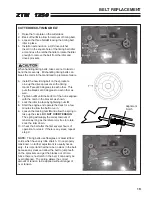
Page 19: ...ct the electric clutch from the wire harness at plug P 3 Remove the carriage bolts securing torque restraint Q to the clutch 4 Insert the square drive end of a 3 8 ratchet or breaker bar into the square hole in the idler arm and use the ratchet handle to rotate the idler assembly enough to remove the belt from the idler and gearbox pulley 5 Work the belt out of the space between the gearbox pulley...

Page 20: ...belt in the preceding section 2 Use a 9 16 wrench on the bolt B securing the idler pulley to rotate the idler arm enough to remove the belt from the idler and pump pulleys Finish removing the belt from the engine pulley 3 Install the new belt by doing steps 1 and 2 in reverse order PUMP PUMP BELT 1 Raise the seat and grass collection hopper or utility box 2 Remove the Engine Pump belt from the pum...

Page 21: ...ut N until the bottom of the nut is aligned with the notch in the bracket as shown 7 Lock the idler in place by tightening nuts B 8 Start the engine and operate the deck for a few minutes to allow the belt to run in 9 Loosen the locking nuts B and allow the spring to take up the slack DO NOT OVER TENSION The spring will supply the correct amount of tension as long as the idler arm is free to rotat...

Page 22: ...n the gearbox spindle idler 3 Use the ratchet handle R to rotate the idler enough to secure it in place with a phillips screwdriver through the hole in the idler arm and desk top Remove the idler from the idler arm Remove the gearbox mounting bolts and loosen the front bolts Remove the belt from the blade spindle pulley and work it out from under the gear box 4 Install the new belt by doing steps ...

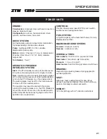
Page 23: ...n cast iron sleeves Aluminum head Configuration 4 stroke horizontal shaft V twin cylinder overhead valve air cooled DRIVE SYSTEM Full hydrostatic pump and wheel motor combination for independently controlled drive wheels Pump Hydrogear BDP 10L 10cc variable displacement piston pump Motors Eaton Char Lynn 11 9 cu in displacement W series Direct drive 1 1 4 31 8mm diameter output shaft Turn Radius T...

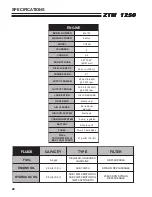
Page 24: ... E R U T C A F U N A M r e l h o K L E D O M S 5 2 H C S R E D N I L Y C 2 G N I L O O C r i A E K O R T S E R O B 4 6 2 7 2 3 m m 7 6 3 8 T N E M E C A L P S I D c c 5 2 7 n i u c 4 4 N O I S S E R P M O C 1 9 R E W O P T U P T U O W k 4 8 1 p h 5 2 m p r 0 0 6 3 E U Q R O T T U P T U O m N 4 5 b l t f 5 9 3 m p r 0 0 4 2 N O I T A C I R B U L E R U S S E R P L L U F R O N R E V O G l a c i n a h...

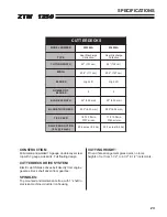
Page 25: ... from 1 1 2 to 4 1 2 in 1 2 increments S K C E D R E T T U C R E B M U N L E D O M A 4 0 2 4 5 9 A 4 0 8 4 5 9 E P Y T e g r a h c s i D r a e R n o i t c e l l o C e g r a h c s i D r a e R n o i t c e l l o C H T D I W G N I T T U C m c 7 0 1 2 4 m c 2 2 1 8 4 H T D I W m c 1 1 1 8 3 4 m c 7 2 1 5 9 4 S E D A L B t f i L h g i H t f i L h g i H F O R E B M U N S E D A L B 2 2 H T G N E L E D A L...

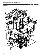
Page 26: ...24 ZTM 1250 ZTM 1250 ZTM 1250 ZTM 1250 ZTM 1250 ENGINE FRAME ASSEMBLY FIGURE 1 ...

Page 27: ...0 BOLT HEX 3 8 16X1 28 27 64229 03 LOCKNUT NYLON 3 8 16 28 28 38219 SPRING TENSION 1 29 64123 100 BOLT HEX 3 8 16X2 1 4 1 30 2222042 7 BRKT HANGER ENGINE 2 31 2720833 7 BRKT GEARBOX SUPPORT 1 32 64163 31 WASHER 5 33 64197 018 BOLT TDFM 7 16 14X1 1 4 4 34 2226030 7 WLDMT PLATE PUMP 1 35 4136748 S FRAME W LBLS STEINER 1 36 2222074 7 SUPPORT FUEL TANK 1 37 64197 003 BOLT TDFM 3 8 16X1 00 4 38 48024 1...

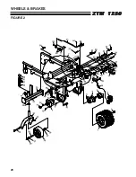
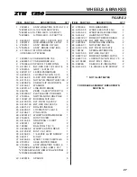
Page 28: ...26 ZTM 1250 ZTM 1250 ZTM 1250 ZTM 1250 ZTM 1250 WHEELS BRAKES FIGURE 2 ...

Page 29: ...FM 10 32X1 2 2 24 64123 100 BLT HEX 3 8 16X2 1 4 4 25 38371 02 BRG NYLINER 5 8 2 26 64229 03 LOCKNUT NYL 3 8 16 6 27 64188 41 PIN CLEVIS 1 28 2226012 7 WLDMT SUBFRAME REAR 1 29 2188135 DUST COVER 1 30 64144 24 SNAP RING 1 00 EXT 1 31 2223017 SPACER 2 32 148042 BALL BRG 1 00 10 2 33 2226005 2 WLDMT CASTER REAR 1 34 64123 221 BOLT 1 2 13X10 1 35 64152 23 1 4 20X3 8 LG SP SCREW 2 36 64221 1 E CLIP 2 ...

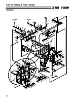
Page 30: ...28 ZTM 1250 ZTM 1250 ZTM 1250 ZTM 1250 ZTM 1250 FRONT PANEL PUSH ARMS FIGURE 3 ...

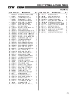
Page 31: ...05 BOLT HEX 5 16 24X4 2 27 64163 55 WSHR 328X 75X14 GA 6 28 38304 02 BRG FLGD PLASTIC 2 29 2720977 SPRING COMPRESSION 2 30 64229 08 LOCKNUT NYLON 5 16 24 2 31 64025 03 NUT HEX 5 16 24 6 32 2228065 DAMPER CONTROL 2 33 38020N CLEVIS YOKE 5 16 PLATE 2 34 64188 02 PIN CLEVIS 5 16X1 2 35 64152 46 SCR SLT HH 10 24X1 2 4 36 64025 15 NUT HEX 10 24 KEPS 4 37 64123 07 BOLT HEX 1 4 20X1 1 2 2 38 64163 03 WSH...

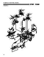
Page 32: ...30 ZTM 1250 ZTM 1250 ZTM 1250 ZTM 1250 ZTM 1250 PUMPS CONTROL PANEL FIGURE 4 ...

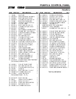
Page 33: ...270 01 BOLT MET M10 1 5 X 30 2 37 2228037 01 TURNBUCKLE 134 0 1 38 4131296 ASSY IDLER PTO 1 INCLUDES ITEM 41 75 76 39 64123 219 BOLT 3 8 16x6 1 40 38297 IDLER 5 OD FLANGED 1 41 4127999 SEAL 16 X 24 X 7 1 42 64163 46 WSHR 383 393X 88X7GA 2 43 64025 02 NUT HEX 5 16 18 2 44 2228037 02 TURNBUCKLE 364 0 1 45 2308133 SPRING EXTENSION 1 46 64152 47 SCR SLT HH 10 24X3 8 5 47 64025 33 NUT HEX 5 16 24 LH 2 ...

Page 34: ...32 ZTM 1250 ZTM 1250 ZTM 1250 ZTM 1250 ZTM 1250 BLOWER FUEL TANK FIGURE 5 ...

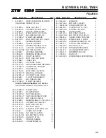
Page 35: ...8 3 BLT CRG 3 8 16X1 2 28 2721889 7 WLDMT BLOWER 1 USE BLOWER ASSEMBLY KIT 970206 INCLUDES ITEMS 10 16 28 29 33 37 29 2721892 7 WLDMT FAN 1 30 2228025 BLOWER INLET 1 31 2222139 7 PLATE BACKING 2 32 2222140 7 PLATE BACKING NTCHD 1 33 64018 23 BLT CRG 3 8 16X3 4 4 34 4128004 BEARING BALL 10 X 26 X 8A 2 35 64237 05 LOCKNUT NYL M8 1 25 1 36 64123 50 BOLT HEX 3 8 16X1 4 37 64141 4 NUT WLF 3 8 16 4 38 6...

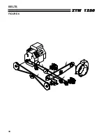
Page 36: ...34 ZTM 1250 ZTM 1250 ZTM 1250 ZTM 1250 ZTM 1250 BELTS FIGURE 6 ...

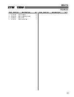
Page 37: ...RT NO DESCRIPTION QTY ITEM PART NO DESCRIPTION QTY 35 ZTM 1250 ZTM 1250 ZTM 1250 ZTM 1250 ZTM 1250 BELTS FIGURE 6 1 2721068 BELT PUMP 2 2 2721069 BELT ENGINE PUMP 1 3 2721065 BELT PTO 1 4 2721067 BELT BLOWER 1 ...

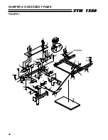
Page 38: ...36 ZTM 1250 ZTM 1250 ZTM 1250 ZTM 1250 ZTM 1250 BUMPER GRASSBOX FRAME FIGURE 7 ...

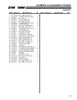
Page 39: ...LINDER GAS 1 12 64188 02 PIN CLEVIS 5 16X1 1 13 64168 2 HAIRPIN COTTER 4 14 64188 42 PIN CLEVIS 5 16X3 50 1 15 2223037 SPACER 11 13X8 18X33 0 2 16 2721080 7 BRKT GRASSBOX RH 2 17 2721079 7 BRKT GRASSBOX LH 2 18 64123 70 BLT HEX 3 8 16X1 1 2 2 19 64163 31 WASHER 25 64X1X12 1 20 64188 33 PIN CLEVIS 3 8X1 1 21 2720952 SPACER 4 22 2721078 7 GRASSBOX DEFLECTOR 1 23 64152 23 1 4 20X3 8 LG SP SCREW 6 24 ...

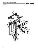
Page 40: ...38 ZTM 1250 ZTM 1250 ZTM 1250 ZTM 1250 ZTM 1250 HEAVY DUTY AIR CLEANER FIGURE 8 ...

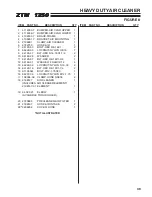
Page 41: ... 2 8 64229 03 LOCKNUT NYLON 3 8 16 7 9 64123 47 BLT HEX 5 16 18X1 1 4 2 10 64163 29 WASHER 2 11 64123 87 BLT HEX 3 8 16X1 3 4 1 12 64163 31 WASHER 25 64X1X12 4 13 64229 02 LOCKNUT NYLON 5 16 18 2 14 64123 16 BLT HEX 3 8 16X1 1 4 2 15 A1105061 BOLT M12 1 75X30 1 16 64237 06 LOCKNUT NYLON M12 1 75 1 17 108094 09 CLAMP HOSE SAE36 4 18 2198147 AIR CLEANER 1 INCLUDES AIR CLEANER ELEMENT 2198147 01 ELEM...

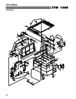
Page 42: ...40 ZTM 1250 ZTM 1250 ZTM 1250 ZTM 1250 ZTM 1250 GRASSBOX FIGURE 9 ...

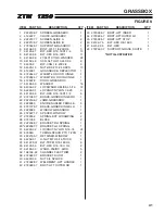
Page 43: ...18X1 1 2 6 21 2721080 7 BRACE GRSBX HINGE RH 1 22 2222199 7 JAMB GRASSBOX 1 23 2228080 KNOB KNURLED FEMALE 3 24 2721079 7 BRACE GRSBX HINGE LH 1 25 2228082 WINDOW GRASSBOX 1 26 2720971 7 SPACER WINDOW 2 27 2722332 SPRING EXT W DAMPING 2 28 2721056 BLOCK 2 29 2222098 7 BRACKET RH SPRING 1 30 2222097 7 BRACKET LH SPRING 1 31 64229 02 LOCKNUT NYLON 5 16 18 24 32 43094A TUBING SPACR PTO T 20N 2 33 222...

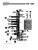
Page 44: ...42 ZTM 1250 ZTM 1250 ZTM 1250 ZTM 1250 ZTM 1250 ELECTRICAL FIGURE 10 ...

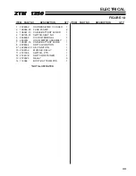
Page 45: ...061 10 CABLE BATTERY 49 RED 1 4 158135 01 SWITCH SEAT NO 1 5 2308095 COVER TERMINAL 1 6 48030N HOUR METER ASSEMBLY 1 7 108061 14 CABLE BATTERY 45 BLK 1 8 2228044 SWITCH IGNITION 1 9 2228044 01 KEY IGNITION 1 10 2188154 MODULE DELAY 1 11 2721505 SWITCH PTO 1 12 2188178 SWITCH RETAINER 1 13 2722325 RELAY 3 14 112386 BOOT BAT TERM POS 1 NOT ILLUSTRATED ELECTRICAL FIGURE 10 ...

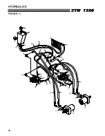
Page 46: ...44 ZTM 1250 ZTM 1250 ZTM 1250 ZTM 1250 ZTM 1250 HYDRAULICS FIGURE 11 ...

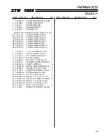
Page 47: ...GH TEMP HSE 2 50 1 6G 69053 05 3 8 HIGH TEMP HSE 2 25 1 7 58026 01 3 WAY CONNECTOR 3 8 2 8 2228085 HOSE FORMED 3 8 ID 1 9 69060 01 FTG BARB 9 16X3 8 ST 1 10 4117905 01 MOTOR WHEEL 2 11 48089 02 FTG STR 10 ORB X 8 JIC 4 12 2228172 CONNECTOR 3 8 STRAIGHT 1 13 88042 04 CLAMP HOSE 5 8 16 14 108035 01 ELBOW ADJUSTABLE3 4 16 2 15 64229 01 LOCKNUT NYLON 1 4 20 2 16 4121333 PUMP HYDRO BDP 10A 440 1 17 158...

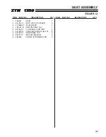
Page 48: ...46 ZTM 1250 ZTM 1250 ZTM 1250 ZTM 1250 ZTM 1250 SEAT ASSEMBLY FIGURE 12 ...

Page 49: ...0 ZTM 1250 SEAT ASSEMBLY 1 198057 SEAT 1 2 64139 16 BOLT WLF 5 16 18X5 8 4 3 4126808 7 PLATE SEAT 1 4 158135 01 SWITCH SEAT NO 1 5 64152 23 1 4 20X3 8 LG SP SCR 4 6 33138 09 PIN CLEVIS GRVD 38x1 31 2 7 64144 30 SNAP RING 375 2 8 38371 01 BRG NYLINER 3 8 2 9 48228A CABLE CLIP INSULATED 2 FIGURE 12 ...

Page 50: ...48 ZTM 1250 ZTM 1250 ZTM 1250 ZTM 1250 ZTM 1250 DECALS FIGURE 13 ...

Page 51: ...TM 1250 DECALS FIGURE 13 1 2000691 LBL HYDR OIL FILL 1 2 4124228 LABEL CONTROL PANEL 1 3 2000735 LABEL OPER MAN 1 4 2000774 LABEL PARK BRAKE 1 5 2000590 LABEL WARN BATTERY 1 6 2000775 LABEL DANGER 1 7 4136745 LABEL GRASSBOX RH ZTM 1 8 4136746 LABEL GRASSBOX LH ZTM 1 9 4128372 LABEL STEINER DIECUT 1 ...

Page 52: ...50 ZTM 1250 ZTM 1250 ZTM 1250 ZTM 1250 ZTM 1250 OPTIONAL FILL INDICATOR 970145 FIGURE 14 ...

Page 53: ...BLT HEX 1 4 20X1 2 8 2228058 MOTOR WIPER 1 9 2228061 HARNESS FILL INDICATOR 1 10 64152 46 SCR SLT HH 10 24X1 2 3 11 64002 02 LOCKWSHR TTH EXT 10 1 12 2222166 7 BRACKET PADDLE MTG 1 13 64025 15 NUT HEX 10 24 3 14 64123 68 BOLT HEX 5 16 18X1 7 15 64163 55 WASHER 11 16 64229 02 LOCKNUT NYL 5 16 18 7 17 2222160 7 BRACKET MOTOR MTG 1 18 2228059 ALARM AUDIBLE 1 19 48228 07 CLIP CABLE INSULATED 5 20 6416...

Page 54: ...52 ZTM 1250 ZTM 1250 ZTM 1250 ZTM 1250 ZTM 1250 HYDROGEAR PUMP FIGURE 15 ...

Page 55: ...EW M6 1 0 X 20 2 15 2513030 BYPASS VALVE KIT BLANK 1 18 70521 2721615 07 PUMP SHAFT KIT 1 19 50315 BALL BEARING 17 X 40 X 12 1 20 51161 LIP SEAL 17 x 40 x 12 1 21 50951 SPACER 1 22 50329 RETAINING RING 1 25 70331 38345 12 CYLINDER BLOCK KIT 1 29 2003014 BLOCK SPRING 1 30 2003017 BLOCK THRUST WASHER 1 31 51246 2721615 09 VALVE PLATE 1 32 2003087 188059 11 SWASH PLATE 1 34 50551 2721615 11 BALL THRU...

Page 56: ...54 ZTM 1250 ZTM 1250 ZTM 1250 ZTM 1250 ZTM 1250 BRAKE ASSEMBLY FIGURE 16 ...

Page 57: ...AND 2188148 BRAKE ASSEMBLIES 2188147 01 BRACKET MACHINED 1 2188147 02 PAD CAM SIDE 1 2188147 03 PAD SUPPORT 1 2188147 04 SPRING LEVER RETAINER 1 2188147 05 HOUSING 1 2188147 06 CAM LH 1 2188147 07 PIVOT PIN 1 2188147 08 PAD CARRIER SIDE 1 2188147 09 PAD SUPPORT 1 2188147 09 PAD SUPPORT 1 2188148 01 CAM RH 1 BRAKE ASSEMBLY FIGURE 16 ...
Page 58: ...n a Textron company is built to exacting standards ensured by ISO 9001 and ISO 14001 registration at all our manufacturing locations A worldwide dealer network and factory trained technicians backed by Textron Parts Xpress provide reliable high quality product support ...

Reviews: