


11
ZTM 1250
ZTM 1250
ZTM 1250
ZTM 1250
ZTM 1250
SPARK PLUGS
Remove each plug and check condition.
–
Good operating conditions are indicated if the plug has a light coating of grey or tan deposit.
–
A white blistered coating indicates overheating. A black coating indicates an “over rich” fuel mixture.
Both may be caused by a clogged air cleaner or improper carburetor adjustment.
–
Do not sandblast, wire brush or otherwise attempt to repair a plug in poor condition. Best results are
obtained with a new plug.
–
Set plug gap as specified in engine manual..
MAINTENANCE
ENGINE OIL
Do not perform engine maintenance without the
engine off, spark plug wires disconnected and PTO
disengaged.
AFTER FIRST FIVE (5) HOURS
While the engine is warm:
1. Remove drain cap
D
and drain the crankcase.
Dispose of used oil in accordance with local
requirements.
2. Clean and replace the cap.
3. Change oil filter.
4. Fill the crankcase with fresh oil to the full mark.
Do not overfill. See engine manual for oil
specifications.
DAILY
1. Check oil level with the dipstick.
2. If oil is needed, add fresh oil of proper viscosity
and grade. See engine manual for oil
specifications. Do not overfill.
3. Replace dipstick before starting engine.
PERIODIC OIL CHANGES
1. See engine manual for oil and filter change
intervals after the break-in period.
2. Follow instructions for first oil change, above.
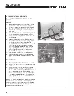
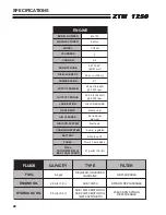
FUEL FILTER
An inline fuel filter
S
is located at the right side of the
engine. Inspect at every oil change to make sure it
is clean and unobstructed. Replace if dirty.
Summary of Contents for 442105
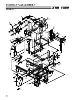
Page 26: ...24 ZTM 1250 ZTM 1250 ZTM 1250 ZTM 1250 ZTM 1250 ENGINE FRAME ASSEMBLY FIGURE 1 ...
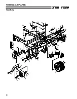
Page 28: ...26 ZTM 1250 ZTM 1250 ZTM 1250 ZTM 1250 ZTM 1250 WHEELS BRAKES FIGURE 2 ...
Page 30: ...28 ZTM 1250 ZTM 1250 ZTM 1250 ZTM 1250 ZTM 1250 FRONT PANEL PUSH ARMS FIGURE 3 ...
Page 32: ...30 ZTM 1250 ZTM 1250 ZTM 1250 ZTM 1250 ZTM 1250 PUMPS CONTROL PANEL FIGURE 4 ...
Page 34: ...32 ZTM 1250 ZTM 1250 ZTM 1250 ZTM 1250 ZTM 1250 BLOWER FUEL TANK FIGURE 5 ...
Page 36: ...34 ZTM 1250 ZTM 1250 ZTM 1250 ZTM 1250 ZTM 1250 BELTS FIGURE 6 ...
Page 38: ...36 ZTM 1250 ZTM 1250 ZTM 1250 ZTM 1250 ZTM 1250 BUMPER GRASSBOX FRAME FIGURE 7 ...
Page 40: ...38 ZTM 1250 ZTM 1250 ZTM 1250 ZTM 1250 ZTM 1250 HEAVY DUTY AIR CLEANER FIGURE 8 ...
Page 42: ...40 ZTM 1250 ZTM 1250 ZTM 1250 ZTM 1250 ZTM 1250 GRASSBOX FIGURE 9 ...
Page 44: ...42 ZTM 1250 ZTM 1250 ZTM 1250 ZTM 1250 ZTM 1250 ELECTRICAL FIGURE 10 ...
Page 46: ...44 ZTM 1250 ZTM 1250 ZTM 1250 ZTM 1250 ZTM 1250 HYDRAULICS FIGURE 11 ...
Page 48: ...46 ZTM 1250 ZTM 1250 ZTM 1250 ZTM 1250 ZTM 1250 SEAT ASSEMBLY FIGURE 12 ...
Page 50: ...48 ZTM 1250 ZTM 1250 ZTM 1250 ZTM 1250 ZTM 1250 DECALS FIGURE 13 ...
Page 52: ...50 ZTM 1250 ZTM 1250 ZTM 1250 ZTM 1250 ZTM 1250 OPTIONAL FILL INDICATOR 970145 FIGURE 14 ...
Page 54: ...52 ZTM 1250 ZTM 1250 ZTM 1250 ZTM 1250 ZTM 1250 HYDROGEAR PUMP FIGURE 15 ...
Page 56: ...54 ZTM 1250 ZTM 1250 ZTM 1250 ZTM 1250 ZTM 1250 BRAKE ASSEMBLY FIGURE 16 ...