in possible personal injury. The user is responsible for preparing the installation
conditions for the machine and for the installation itself.
After mounting the machine, check that the hook is properly mounted and that
the latch is closed. Always check that the brake operates correctly each time a load
is lifted. To do this, hang a test load (approx. 10% of the allowable load) and raise
and lower it several times to ensure that it will not slide when the lift/lower stops.
Always check the position of the chain - that it is not twisted, the correct position
of the chain is when the link joints are aligned.
3.3.
Working with the unit
OPERATION - lifting / lowering
Inspect daily before use and make sure load chain, sprockets and bearings are
properly lubricated.
Position the hook directly over the load so that the chain is not under tension.
• To pull in the load, set the shift switch to the left, then alternately lift the drive
lever up and push down.
• To lower the load, set the shift switch to the right, then alternately lower the
drive lever down and push up.
• Setting the shift switch to the middle position will apply the brake.
Lifting/lowering can be stopped at any point.
Stop work immediately if the chain becomes jammed or if there is any other
malfunction. Notify a competent person who can remove the load and perform
steps to restore normal operation. Designate a safety area around the machine
and under the load to prevent unauthorized persons from entering or remaining
in the area. Return the machine to an authorized service center.
When unlocking a locked load on the ascender, additional force may be
required to release friction between the brake components.
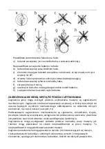
MOUNTING THE LOAD
Pay special attention to how the load is hooked onto the ascender hook. The
figure below shows proper and improper attachment methods.
Summary of Contents for SBS-FZ 9000/1.5
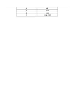
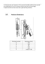
Page 13: ...C 68 D 410 E 150 H mind 780 ...
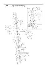
Page 14: ...3 8 Explosionszeichnung ...
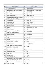
Page 26: ...3 8 Assembly drawing ...
Page 39: ...3 8 Rysunek złożeniowy ...
Page 51: ...3 8 Výkres sestavy ...
Page 63: ...C 68 D 410 E 150 H 780 au minimum ...
Page 64: ...3 8 Dessin d assemblage ...
Page 76: ...3 8 Esploso ...
Page 89: ...3 8 Dibujo de conjunto ...
Page 101: ...3 8 Szerelési rajz ...
Page 113: ...3 8 Samlingstegning ...


