Speedclean Eco 30
2011_V1
page 9 of 16
5.3 Installation
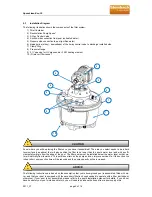
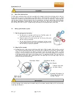
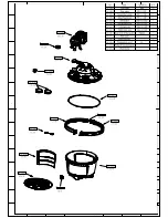
Diagram
The following illustration shows the components of the filter system.
1) Filter Container
2) Recirculation Pump
Speed
3) 3-Way Central Valve
4) Suction-side connection from pool (untreated water)
5) Pressure side connection to pool (purified water)
6) drainage line (slurry) - downstream of the 3-way central valve to discharge installed side
7) Clamp Ring
8) Pressure Gauge
9) 2 ¼” opening for UV pipes and/or 3 KW heating element
10) Drain vor filter vessel
Know where you will be placing the filter once you have it assembled? The area you select needs to be a hard
level surface (see above) that will also position the filter to be lower than the pool’s water level and with a suffi-
cient safety margin from the edge of the pool. The filter pump must be installed below the water level so that wa-
ter will naturally flow towards it. This puts less strain on the pump and can improve service life. If the suction line
is kept short, pump suction time will be reduced and the pump capacity will be increased
The following instructions are based on the assumption that your above-ground pool is assembled, filled with wa-
ter, and that your pool is equipped with the necessary filtration hoses needed to operate with a filter (cartridge or
otherwise). If your pool is not assembled, please refer to the pool’s installation manual for details. If you do not
have hoses for your pool’s intake and return, you will need to purchase the hoses from a pool supply store.
CAUTION
ADVICE
1
2
3
4
5
6
7
8
9
10
Summary of Contents for Speedclean Eco 30
Page 17: ......


