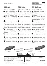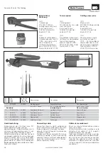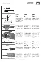
(ill.13)
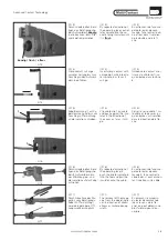
Durch wiederholtes Betä-
tigen des Betätigungshe-
bels Aufweitdorn
in die Buchsen- bzw. Ste-
ckerisolation einziehen.
bündig
(ill.14)
Insert crimp contact with
crimped-on wire into dila-
tor spindle 6 as far as it
will go.
(ill.15)
Kabelklemmung 1 auf Ka-
bel klemmen und bis zum
Anschlag in Pfeilrichtung
an die Isolation schieben.
(ill.16)
Durch wiederholtes Betä-
tigen des Betätigungshe-
bels 3 Aufweitdorn 6 in
das Werkzeug ein- und
die Isolation auf das Kabel
aufziehen.
(ill.17)
Durch Abnahme des Ma-
gazins vom Betätigungs-
hebel (in Pfeilrichtung)
wird eine geringere Öff-
nungsweite ermöglicht
(ill.13)
By repeated actuation of
the operating lever, pull di-
lator spindle into the so-
cket or plug insulator until
it is
.
flush
(ill.13)
En actionnant de façon ré-
pétée le levier de com-
mande, faire rentrer le cô-
ne à fleur dans l'isolation
de la douille ou de la fi-
che.
(ill.14)
Crimpkontakt mit ange-
crimpter Leitung bis zum
Anschlag in den Aufweit-
dorn 6 einführen.
(ill.14)
Introduire le contact à ser-
tir avec le câble serti jus-
qu'en butée dans le cône
6.
(ill.15)
Serrer le serre-câble 1 sur
le câble et le pousser jus-
qu'en butée sur l'isolation
dans la direction de la flè-
che.
(ill.15)
Clip cable clip 1 on cable
and push against the insu-
lator in the direction of
the arrow as far as it will
go.
(ill.16)
By repeated actuation of
the operating lever 3,
push the dilator spindle 6
into the tool and pull the
insulator onto the cable.
(ill.16)
En actionnant de façon ré-
pétée le levier de com-
mande 3, faire rentrer le
cône 6 dans l'outil et mon-
ter l'isolation sur le câble.
(ill.17)
The removal of the maga-
zine from the operating le-
ver (in direction of arrow)
allows a smaller opening
width.
(ill.17)
En enlevant le magasin
du levier de commande
(dans le sens de la flè-
che), on peut obtenir une
plus faible largeur d'ou-
verture.
5/8
www.multi-contact.com
Advanced Contact Technology
ill.13
bündig / flush / à fleur
ill.14
1
ill.15
1
ill.16
ill.17

