background image

F

FC

CC

C  C

Co

om

mp

plliia

an

nc

ce

e  S

Stta

atte

em

me

en

ntt

This equipment has been tested and found to comply with the limits for a Class B digital
device, pursuant to part 15 of the FCC Rules. These limits are designed to provide
reasonable protection against harmful interference in a residential installation. This
equipment generates, uses and can radiate radio frequency energy and, if not installed
and used in accordance with the instructions, may cause harmful interference to radio
communications. However, there is no guarantee that interference will not occur in a
particular installation. If this equipment does cause harmful interference to radio or
television reception, which can be determined by turning the equipment off and on, the
user is encouraged to try to correct the interference by one or more of the following
measures:

• Reorient or relocate the receiving antenna.

• Increase the separation between the equipment and receiver.

• Connect the equipment into an outlet on a circuit different from that to which the 

receiver is connected.

• Consult the dealer or an experienced radio/TV technician for help.

U

Us

se

e  o

off  T

Trra

ad

de

em

ma

arrk

ks

s,,  R

Re

eg

giis

stte

erre

ed

d  T

Trra

ad

de

em

ma

arrk

ks

s,,  a

an

nd

d

o

otth

he

err  P

Prro

otte

ec

ctte

ed

d  N

Na

am

me

es

s  a

an

nd

d  S

Sy

ym

mb

bo

olls

s

This manual may make reference to trademarks, registered trademarks, and other
protected names and/or symbols of third-party companies not related in any way to
StarTech.com. Where they occur these references are for illustrative purposes only and
do not represent an endorsement of a product or service by StarTech.com, or an
endorsement of the product(s) to which this manual applies by the third-party company in
question. Regardless of any direct acknowledgement elsewhere in the body of this
document, StarTech.com hereby acknowledges that all trademarks, registered
trademarks, service marks, and other protected names and/or symbols contained in this
manual and related documents are the property of their respective holders.

Summary of Contents for PCI2S650DVLP

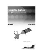
Page 1: ...Dual Voltage Serial Card PCI2S650DVLP Instruction Manual Actual product may vary from photo 2 Port 16650 Low Profile Dual Voltage Serial Card ...

Page 2: ...quipment and receiver Connect the equipment into an outlet on a circuit different from that to which the receiver is connected Consult the dealer or an experienced radio TV technician for help U Us se e o of f T Tr ra ad de em ma ar rk ks s R Re eg gi is st te er re ed d T Tr ra ad de em ma ar rk ks s a an nd d o ot th he er r P Pr ro ot te ec ct te ed d N Na am me es s a an nd d S Sy ym mb bo ol ...

Page 3: ...Before You Begin 1 System Requirements 1 Contents 1 Installation 2 Installing the Serial Card 2 Installing the drivers 2 Verifying installation 3 COM Port configuration 3 Specifications 4 Troubleshooting Guide 5 Technical Support 6 Warranty Information 6 Instruction Manual i ...

Page 4: ... supports both 64 bit 3 3V and 32 bit 5V PCI High speed serial data transfers up to 921Kbps 128K transmit receive FIFO buffer helps improve overall system performance IRQ sharing eliminates IRQ conflicts Low profile design saves space B Be ef fo or re e Y Yo ou u B Be eg gi in n System Requirements A computer with an available PCI or PCI X 64 bit PCI port A computer running Windows 95 98SE NT ME 2...

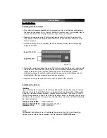
Page 5: ...oining socket previously covered by metal bracket using the correct size screw please consult documentation that accompanied purchase of computer 5 Replace the computer cover and re connect all power to the computer Installing the drivers Windows Upon rebooting the computer for the first time following the installation of the serial card Windows will detect the PCI Serial card and prompt for drive...

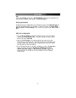
Page 6: ...t you want to configure located under Ports COM LPT Using the right mouse button click on the port and select Properties 2 Open the Port Settings tab to configure the Bits per second Data bits Parity Stop bits and Flow control For further information on the appropriate settings in these fields please consult the documentation that was included with the purchase of the serial device 3 To set advanc...

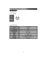
Page 7: ... X Maximum Data Transfer Rate 921 6 Kbps Chipset SUN1889 Operating systems supported Windows 9x ME NT 2000 XP 2003 Linux 2 0 x 2 2 x 2 4 x 2 6 x DOS Operating temperature 0 C 57 C Storage temperature 20 C 85 C Baud Rate 75bps 921 6Kbps Data bits 4 5 6 7 8 Stop bits 1 1 5 2 Parity Even Odd None Mark Space Flow Control None Xon Xoff Hardware Signal type TxD RxD RTS CTS DTR DSR DCD RI GND Product dim...

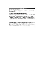
Page 8: ...booting the computer Upon rebooting the computer should detect the card and ask that the necessary drivers be installed Follow the installation steps outlined in Installation The peripheral device s connected to the serial card are functioning slowly poorly From within the Device Manager browse through the settings for the installed port Under Advanced Port Settings set the Receive Transmit Buffer...

Page 9: ...r replacement with equivalent products at our discretion The warranty covers parts and labor costs only StarTech com does not warrant its products from defects or damages arising from misuse abuse alteration or normal wear and tear Limitation of Liability In no event shall the liability of StarTech com Ltd and StarTech com USA LLP or their officers directors employees or agents for any damages whe...

Page 10: ...on of computer parts cables server management solutions and A V products and serve a worldwide market through our locations in the United States Canada the United Kingdom and Taiwan Visit www startech com for complete information about all our products and to access exclusive interactive tools such as the Parts Finder and the KVM Reference Guide StarTech com makes it easy to complete almost any IT...

Reviews: