background image


Starke Arvid AB                                                                      Tel: +46 522 - 22 000                                                Fax: +46 522 - 22 344 
Lyckåsvägen 3                                                                      

www.starkearvid.se                                                   [email protected]

SE-459 30 Ljungskile 


Sida 

12

 av 

25


The manual valve (suction/release valve) 


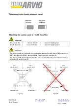
Attaching the suction pads to the KS VacuFlex 

Attention! 

- Blue hose line  

 vacuum circuit1  

=  

vacuum coupling blue


- Black hose line   =  

vacuum circuit2  

=  

vacuum coupling black


Attention! 

The suction pads on the device must always be attached in such a way that vacuum cir-
cuit 1 and vacuum circuit 2 are connected in every suction row see (A). 

The suction pads must never be attached in such a way that only one vacuum circuit is 
connected in suction row (B). 


Figure A 


Figure B 

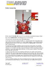
Positon 


Position 

Suction 


Release 

Suction row 2 

black 

vacuum circuit 2 

blue 

vacuum circuit 1 

black 

vacuum circuit 2 

Suction row 1 

Suction row 2 

blue 

vacuum circuit 1 

blue 

vacuum circuit 1 

blue 

vacuum circuit 1 

Suction row 1 

black 

vacuum circuit 2 

Suction row 2 

black 

vacuum circuit 2 

Summary of Contents for Vakuflex 280

Page 1: ... 522 22 000 Fax 46 522 22 344 Lyckåsvägen 3 www starkearvid se office starkearvid se SE 459 30 Ljungskile Operating Instructions Vakuflex 280 Attention Please read the instructions carefully before use Please keep the manual ...

Page 2: ...operating phases 8 Normal operation 8 Special work 9 Safety instructions for special types of danger 9 Electrics 9 Oils greases and other chemical substances 9 COMMISSIONING 10 Charging the battery 11 The manual valve suction release valve 12 Before transporting 13 OPERATION 15 Switching on 16 Working cycle 17 Switching off 20 Charging the battery 20 TROUBLESHOOTING 21 Leak check 22 Leak check for...

Page 3: ... These operating instructions must always be available at the site of use of the Vakuflex 280 These operating instructions must be read and observed by every person responsible for doing work on the Vakuflex 280 for example operation including equipping troubleshooting during operation removal of production waste care maintenance servicing inspection repair and or transport In addition to the oper...

Page 4: ...ding a non return valve a vacu um switch and a checking vacuum gauge Two vacuum pumps will be used to generate a vacuum one pump per vacuum circuit Two vacuum pumps are used to generate the vacuum one vacuum pump each vacuum circuit The vacuum pumps work without oil lubrication and are therefore maintenance free Particularly the device consists of one main frame including four swinging rectangular...

Page 5: ...n when the pressure falls below approx 0 68 This avoids premature draining of the batteries due to the pumps being al lowed to run unnecessarily As accessories for the machine the crane facility and conveying facility are available Mode of operation Switch the machine on using the ON OFF switch 3 Then set the two manual valves to RELEASE The vacuum unit must be positioned on the load to be transpo...

Page 6: ...may result in danger to life and limb of the operator or third parties and impairment of the machine or other property may occur The machine may only be used when in technically perfect condition as authorised The user must be conscious of safety and risks and act in accordance with the instructions Failures which can interfere with safety must be eliminated immediately The Vakuflex 280 is exclusi...

Page 7: ...re of risks If necessary or if required by regulations personal protective equipment should be used Glass should only be transported with the appropriate protective equipment safety shoes protective gloves wrist protectors helmet etc A helmet should be worn at all times when transporting goods above head height All safety and danger instructions on the device should be complied with All safety and...

Page 8: ...ormed by an electrician or by trained personnel under the direction and supervision of an electrician in accordance with the rules of electrical engineering Safety instructions on particular operating phases Normal operation Avoid all unsafe work practices Before starting work become familiar with the working environment at the site of use The working environment includes impediments in the work a...

Page 9: ... flaws immediately Always tighten screw connections loosened during maintenance and repair work Safety instructions for special types of danger Electrics Use only original fuses with the specified current strengths Switch off the machine immediately during malfunctions to the electrical energy supply Work on electrical equipment or operating materials may only be performed by an electri cian or by...

Page 10: ...ction circuit impairing the functioning of the device Never place the machine with mounted suckers with the rubber surfaces of the suckers on sandy or similar ground This could damage the sealing lips of the suckers This would lead to leaks in the suction circuit impairing the functioning of the device Or the grains of sand or similar substances could be pressed into the rubber surfaces leading to...

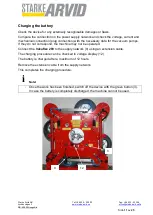
Page 11: ...nection with the necessary data for the vacuum pumps If they do not correspond the machine may not be operated Connect the Vakuflex 280 to the supply network 9 using an extension cable The charging procedure can be checked in voltage display 12 The battery is charged after a maximum of 12 hours Remove the extension cable from the supply network This completes the charging procedure Note Once the w...

Page 12: ...uction pads on the device must always be attached in such a way that vacuum cir cuit 1 and vacuum circuit 2 are connected in every suction row see A The suction pads must never be attached in such a way that only one vacuum circuit is connected in suction row B Figure A Figure B Positon Position Suction Release Suction row 2 black vacuum circuit 2 blue vacuum circuit 1 black vacuum circuit 2 Sucti...
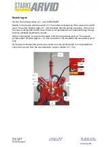
Page 13: ...ing vacuum in the hose system of both vacuum circuits can be checked on the two vacuum meters 5 1 5 2 After a short time a vacuum of at least 0 65 bar should have built up in each tank The vacuum pumps switch off when 0 7 bar vacuum is reached This should be the case after a short time In order to check the vacuum the individual suckers two per vacuum circuit must be blocked from the vacuum reserv...

Page 14: ...the individual suckers and then sucked on To do so the manual valves 2 1 2 2 must be set to SUCTION using the remote control A vacuum of at least 0 65 bar should build up immediately in each vacuum circuit If this happens the machine switch 3 must be switched off Read the achieved vacuum from the two inspection vacu um meters 5 1 5 2 and compare it with a reading taken about 15 minutes later If th...

Page 15: ...ion circuit impairing the functioning of the device Never place the machine with mounted suckers with the rubber surfaces of the suckers on sandy or similar ground This could damage the sealing lips of the suckers This would lead to leaks in the suction circuit impairing the functioning of the device Or the grains of sand or similar substances could be pressed into the rubber surfaces leading to d...

Page 16: ...icates that the pumps are active If this is not the case working with the KS Vacu Power is not permitted see Troubleshooting the sig nal tone indicates insufficient vacuum After a short period a vacuum of at least 0 65 bar should have built up The vacuum pumps switch off when approx 0 7 bar is reached This should be the case after a short time As long as no transported goods are sucked on or the s...

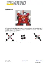
Page 17: ... 17 av 25 Working cycle Determine the position of the carrier frame 7 using the rotating or swivelling device 8 in which the transported goods are to be sucked on Always order the suctions symmetrically in order to hold the device in balance Some examples as follows Position the KS Vakuflex 280 on the goods to be transported 7 8 9 10 ...

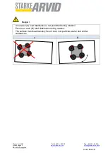
Page 18: ...rvid se office starkearvid seSe SE 459 30 Ljungskile Sida 18 av 25 Danger An uneven A load distribution is not permitted during rotation Ensure an even B load distribution during rotation The surface must be absolutely free of dust rust particles water and similar substances A B ...

Page 19: ... down the load as soon as possible so that it does not fall down The transported goods are guided from the side which means that the operator stands as far as possible from the transported goods in order to guide them To rotate or swivel 8 the transported goods use the appropriate locking mechanism The transported goods must always be positioned according to the drawing B It must also be ensured t...

Page 20: ...wer supply network with regard to voltage current and mechanical connection plug connection with the necessary data for the vacuum pumps If they do not correspond the machine may not be operated Connect the device to the mains power supply at the plug 9 The charging procedure can be checked in voltage display After the charging procedure is completed a value of 100 must be visible in the voltage d...

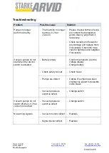
Page 21: ...for any damage and replace them if necessary Check the hose clips for tightness and retighten if necessary Vacuum pumps do not start when the device switch is actuated Battery empty Control mechanism over the voltage display Charge battery Check safety cut out Check fuses Pumps are defect Cables of pumps have been checked by expert for possible cable break Vacuum pressure switch is defect Change s...

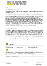
Page 22: ...o the device will not function and may not be put into operation The leak must be corrected immediately or the porous material replaced Leak check without suckers If the result of the test of the entire circuit is negative the next step is to check the vacuum reserve tanks with the supply lines to the vacuum couplings of the individual suckers two per vacuum circuit To do so set the manual valves ...

Page 23: ...for our vacuum lifting devices which includes annual maintenance including testing and certification Please contact us for details Starke Arvid AB The suckers The suckers must be cleaned occasionally with a clean cloth Please do not use a solvent such as gasoline or similar substances Never treat the suckers with talc lubricants or smoothing agents as this impairs the adhesion of the suckers causi...

Page 24: ...vable vacuum as a rule approx 0 7 bar in each vacuum circuit has been achieved the pumps are switched off Read the achieved vacuum from the vacuum meters 5 1 5 2 and record the value in writing The indicator of the vacuum meters 5 1 5 2 is only should only change slightly within the next 15 minutes not more than 5 If the result of this test is positive the vacuum lifting device is tight and you ca...

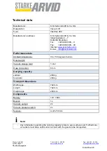
Page 25: ... www ksschulten com E mail info ksschulten com Performance data Ambient temperature 0 to 50 degrees Celsius Dead weight Vacuum storage tank 1 Liter Hose connection 6 mm Carrying capacity vertical 280 kg horizontal 280 kg Transport dimensions Width appx 742 mm Length 742 mm Height appx 230 mm Components Battery 12V 7 0Ah Buzzer 1x Vacuum pumps 2x Vacuum pressure switch 2x Suckers 4 x Ø 250 mm Note ...

Reviews: