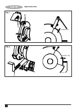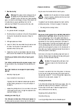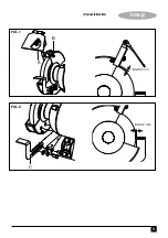
• The adjustment of the work rest shall be done gradually
so as to compensate the wear of the wheel, keeping the
distance between the work rest and the wheel as small
as possible, but in any case not greater than 2mm;
• Allow the tool to cool down after a continuous use of 20
minutes (S2 20min)
• Basic information on grinding wheels
1. Put grinding wheel in individual package, and keep in a
dry and well-ventilated place.
2. Various shortcomings during installation and operation
can lead to bursting of grinding wheels.
3. Ordinary grinding wheels are generally not designed to
withstand a greater lateral load.
4. Tap off cutting debris from the grinding wheel always
leads to damage of the grinding wheel.
5. Grinding wheels which may have an imbalance burst
easily.
6. An unbalance of a grinding wheel can not be completely
removed by withdrawing with a diamond dresser.
7. Incorrectly stored grinding wheels can burst immediately
after switching on, or individual small fragments fly away
like a bullet.
• Releasing jammed accessories. Release the pressure
on work piece, grinding wheels will return running.
• Lifting and transportation. Stop and disconnect machine.
Use two hands to lift up machine from two sides of
bottom of bearing housing.
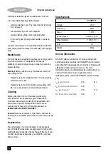
• The work piece should be suitable for opening size
between wheels and plate. The machine is designed
and manufactured exclusively for grinding metals using
properly authorized grinding wheels. The grinding
machine must be used exclusively for this purpose.
Package Contents
The package contains:
1 Bench Grinder
2 Tool Rests
2 Eye Shields
2 Mounting Brackets
1 Instruction Manual
Features
This tool includes some or all of the following features.
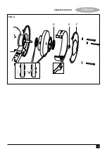
A. Spark Guard
B. Screw
C. Tool Rest
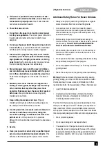
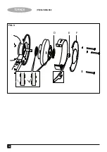
D. Flange
E. Clamping Nut
F. Protective Cover
6
ENGLISH
(Original instructions)
Read
I
nstructions
Manual
U
se Eye
Protection
U
se Ear
Protection
V ........ Volts
A ........ Amperes
H
z .......
H
ertz
W ........
W
atts
min ..... minutes
..... Alternating
Current
..... Direct
Current
n
0
....... No-Load
Speed
...... Class
II
Construction
.... Earthing
Terminal
.... Safety Alert
Symbol
.../min.. Revolutions
or Recipro-
cation per
minute
6. Labels on tool
The label on your tool may include the following symbols:
Position of date barcode
The Date Code, which also includes the year of
manufacture, is printed into the housing.
Example:
2014 XX JN
Year of manufacturing
Summary of Contents for STGB3715
Page 1: ...STGB3715 English Page 3 Turkish Page 11 ...
Page 2: ...ENGLISH 2 Original instructions FIG 1 FIG 2 C MAX 2 mm MAX 2 mm B A ...
Page 3: ...3 ENGLISH Original instructions FIG 3 D E F ...
Page 11: ...11 TÜRKÇE Orijinal talimatlar FIG 1 FIG 2 C MAX 2 mm MAX 2 mm B A ...


