background image

Glossary

141

Summary of Contents for QEL 200

Page 1: ...ww QEL 200 User Guide Wireless Stand Alone ...

Page 2: ...onic or mechanical including photocopying recording or information storage and retrieval systems for any purpose without the express written permission of Stanley Security Solutions Inc This document is distributed as is without warranty of any kind either express or implied respecting the contents of this book including but not limited to implied warranties for the publication s quality performan...

Page 3: ...red antenna impedance for each antenna type indicated Antenna types not included in this list having a gain greater than the maximum gain indicated for that type are strictly prohibited for use with this device Approved antennas are listed below Cet appareil est conforme aux normes d Industrie Canada exempts de licence RSS s Son fonctionnement est soumis aux deux conditions suivantes 1 cet apparei...

Page 4: ...anagement Chapter 3 Wireless System 68 Components at Work for Wireless System 69 Develop a Site Plan 72 Organize Segment Data 73 Prepare Host Computer 75 Install Gateways 76 Gateway Configuration 77 Install Software 81 Configure Software Chapter 4 Wireless Management 116 Page Layout Chapter 5 Service Upgrade Chapter 6 Troubleshoot 126 Lockset Installation 128 Gateway 128 Software Chapter 7 Glossar...

Page 5: ...Contents 5 ...

Page 6: ......

Page 7: ...Overview 1 ...

Page 8: ...oor This system allows remote access to any environment no hardwiring is needed System Components A Stand Alone system has 3 components Component 1 Lockset Exterior Exterior Extérieur Interior Interior Intérieur 2 Core Keyset Core Core Core Operator Key Operator Key Operator Key O C 3 Proximity Cards Place near reader to grant access to factory default locksets Temporary Operator Card 125 kHz x 26...

Page 9: ...der to grant access to factory default locksets Temporary Operator Card 125 kHz x 26 Bit 5 Gateway This device complies with Part 15 of the FCC Rules Operation is subject to the following two conditions 1 this device may not cause harmful interference and 2 this device must accept any interference received including interference that may cause undesired operation FCC ID WEF QZGW001 IC 7713A QZGW00...

Page 10: ...10 Overview 7 Host Computer 8 Mobile Device optional ...

Page 11: ...ndalone Locks 2 Standalone Management Wireless system Please see Chapter 3 for Wireless System setup instructions 1 Develop a Site Plan 2 Organize Segment Data 3 Prepare Host Computer 4 Install Software 5 Install Gateway s 6 Connect Gateway s to Lock s 7 Install Wireless Lock s 8 Understand Lockset Modes 9 Configure Software ...

Page 12: ...12 Overview ...

Page 13: ...Standalone System 2 ...

Page 14: ...d Install Standalone Locksets Steps 1 Check Installation Settings 2 Document Lockset Identification 3 Prepare Doors 4 Install Locksets Check Installation Settings Standalone Locksets are for use inside protected areas For other applications such as outdoor use contact the factory for the appropriate NEMA enclosure Changes or modifications not expressly approved by Stanley Security Solutions could ...

Page 15: ... www stanley com templates Install Locksets Use the installation instructions provided with the lockset package You can also find installation instructions at www stanley com installationinstructions Standalone Management Steps 1 Key Lock Unlock 2 Card Lock Unlock 3 Basic Functionality 4 Add Remove User s 5 Battery Functionality Key Lock Unlock Verify lockset operation by following these steps Ins...

Page 16: ...de 1 Present proximity card twice in rapid succession 2 If ACL contains this card data lock will perform standard unlock sequence 3 Lock will enter Passage Mode accompanied by a visual cue 4 If ACL does not contain this card data a visual cue for Double scan Access Denied will occur along with an audio cue Return to Normal Mode 1 Present proximity card once do not present a second time within two ...

Page 17: ...d a second time within two seconds 2 The card data will be added to the ACL as a normal operator 3 A visual cue for Card Added to Stand Alone ACL will occur along with an audio cue 4 Programming mode counter will reset to 10 seconds Remove User 1 While in Programming Mode present the proximity card twice in rapid succession 2 The card data will be removed from the ACL 3 A visual cue for Card Remov...

Page 18: ...andalone System Low Battery Warning Both visual and audio Low Battery Mode cues will occur when battery power drops below a specified level Note At this point a normal load would last two weeks or less i e 6 ...

Page 19: ...Standalone System 23 ...

Page 20: ...24 Standalone System ...

Page 21: ...Standalone System 25 ...

Page 22: ...26 Standalone System ...

Page 23: ...Standalone System 27 ...

Page 24: ...28 Standalone System ...

Page 25: ...Standalone System 29 ...

Page 26: ...30 Standalone System ...

Page 27: ...Standalone System 31 ...

Page 28: ...32 Standalone System ...

Page 29: ...Standalone System 33 ...

Page 30: ...34 lone System ...

Page 31: ...Standalone System 35 ...

Page 32: ...36 lone System ...

Page 33: ...Standalone System 37 ...

Page 34: ...38 lone System ...

Page 35: ...Standalone System 39 ...

Page 36: ...40 lone System ...

Page 37: ...Standalone System 41 ...

Page 38: ...42 lone System ...

Page 39: ...Standalone System 43 ...

Page 40: ...44 lone System ...

Page 41: ...Standalone System 45 ...

Page 42: ...46 lone System ...

Page 43: ...Standalone System 47 ...

Page 44: ...48 lone System ...

Page 45: ...Standalone System 49 ...

Page 46: ...50 lone System ...

Page 47: ...Standalone System 51 ...

Page 48: ...52 lone System ...

Page 49: ...Standalone System 53 ...

Page 50: ...54 lone System ...

Page 51: ...Standalone System 55 ...

Page 52: ...56 lone System ...

Page 53: ...Standalone System 57 ...

Page 54: ...58 lone System ...

Page 55: ...Standalone System 59 ...

Page 56: ...60 lone System ...

Page 57: ...Standalone System 61 ...

Page 58: ...62 lone System ...

Page 59: ...Standalone System 63 ...

Page 60: ...64 lone System ...

Page 61: ...Standalone System 65 ...

Page 62: ...66 lone System ...

Page 63: ...Standalone System 67 ...

Page 64: ...68 lone System ...

Page 65: ...Standalone System 69 ...

Page 66: ...70 lone System ...

Page 67: ...Standalone System 71 ...

Page 68: ...67 Wireless System 2 ...

Page 69: ... software and gateway configuration for locksets 3 Gateway Connects to the Host Computer through a secure IP address Transfers data signals from Wireless locksets to and from the Host Computer 4 Wireless Lockset Battery operated lockset equipped with Stanley technology that controls user access at the door Communicates with the Gateway and grants user requests according to how they are configured ...

Page 70: ...re Disc Software Quick Start Guide 5 Install Gateway s Gateway Installation Instructions and template Tools listed in the installation Instructions and template 6 Gateway Configuration Gateway Webpage 7 Install Wireless Lock s Lockset Installation Instructions and template Tools listed in the installation instructions and template Core Keyset or Plastic Thumb Core Wireless Card Temporary Operator ...

Page 71: ...ior to the site survey If one is not available through your facilities maintenance or project engineer visit the site to take measurements to create one Gateway Specifications The Gateway is a wireless device connected to the Host computer through a secure IP address similar to the way your computer is connected to the internet It transfers data signals from Wireless Locksets to and from the Host ...

Page 72: ... that do not make it from a lockset to a Gateway because of interference Interference can also reduce lockset battery life due to the constant re broadcasting of packets and lost connections to the gateways To achieve maximum efficiency in wireless system the frequency range must be managed effectively Therefore the installer must know the positions and channels of all the 2 4 GHz wireless devices...

Page 73: ...e Segment Data Steps 1 Collect Gateway and Lockset Information 2 Collect User Information Collect Gateway Information During your site survey you have documented MAC numbers names capacities and physical locations of all gateways and locksets so you can identify and assign them to the correct location within the Stanley Intelli M Software Collect User Information You will need to gather the names ...

Page 74: ... Settings Stanley software can be installed on the following server operating systems Microsoft Windows Vista Servers Microsoft Windows Server 2008 Vista Server Configuration 1 Power up the server 2 Navigate the following path Start Control Panel Programs Turn Windows Features On or Off Internet Information World Wide Web Services Application Development Features 3 Select ASP NET The NET Extensibi...

Page 75: ...e server Image TBD Note If SQL has not been installed Select Yes When prompted create a strong database password Enter a combination of upper case lower case and numbers Select Complete for the Setup Type Click the Install button Click Finish to close the Stanley installer Windows Server 2008 Configuration 1 Power up the server 2 Press the Ctrl Alt Delete keys and enter the server password 3 Navig...

Page 76: ...Wireless System 75 15 Exit the Configuration window 16 Go to Installing The Intelli M Access Software on page 18 ...

Page 77: ...ick Add or Remove Programs 4 Click Add Remove Window Components which can be found onthe left side margin The Windows Component window will be displayed 5 Depending on the Operating System installed select i e check mark either Application Server or Message Queuing along with Accessories And Utilities Refer to Figure 6 Then click Next Image TBD ...

Page 78: ...ant to use a specially designed locked enclosure Contact your dealer for more information Use the template provided with the Gateway package to prepare for installation You can also find the template at www stanley com templates Install Gateway Use the installation instructions provided with the Gateway package You can also find installation instructions at www stanley com templates Verify Operati...

Page 79: ...used a AC to DC adaptor plus a cable the gateway leds will light green only Gateway Configuration Steps 1 Connect Gateway to Network 2 Configure IP Network Settings 3 Gateway Website Connect Gateway to Network Configure IP Network Settings Gateway Website Activity Indicator Ethernet Connection Power Port Power Indicator Link Indicator ...

Page 80: ...o close the Intelli M Access installer Install Wireless Locksets Steps 1 Check Installation Settings 2 Document Lockset Identification 3 Prepare Doors 4 Install Wireless Locksets 5 Test Functionality Check Installation Settings Wireless Locksets are for use inside protected areas For other applications such as outdoor use contact the factory for the appropriate NEMA enclosure Changes or modificati...

Page 81: ...ou can also find installation instructions at www stanley com installationinstructions Test Functionality Verify lockset operation by following these steps Or use a Temporary Operator Card to test functionality Insert the key that is labled O Insert the key that is labled O Insert the key that is labled O Lock Lock Lock Unlock Unlock Unlock Operator Key Operator Key Operator Key Place Temp Card ne...

Page 82: ...want secure interior doors Each secured door also borders two Zones the interior of the floor building and the space you wish to secure You may re use the Inside Zone for the unsecured side of the door and create a new Zone e g Dental Records Room to serve as the name of the secured space When configuring access privileges you will grant access to the Dental Records Room Zone not the Door that bor...

Page 83: ...holders Therefore you can modify the access privileges of a large number of Cardholders with one configuration change You can also change access privileges for a Cardholder by adding removing them from a Group Door Types Image TBD A Door Type is a template that describes the input and output configuration gathered into a single unit Intelli M installs several default Door Types Most or all your Do...

Page 84: ...o a Door via Door Behavior as an unlock schedule to a Person via Group membership to define the hours they may access a Zone or to a Rule to define when it may be active For example when a Schedule is applied to a Door the Door will be unlocked during the Active Time Range blue section and unlocked during the Inactive Time Range white section A Holiday is a single day in which normal business hour...

Page 85: ...ke Google Maps Each Peripheral is supported by a Plugin which is a software module which provides the bridge between Intelli M and the third party device service Use the Rules Engine to control the Peripheral For example you may instruct it to Record video on camera X when a card with invalid credentials are swiped at Door Y Energize output A when input B is raised Show live video in my browser on...

Page 86: ...hange the default password Image TBD Create a Door 1 Log into the system 2 Press Configuration in upper right corner The main page in this section is the Doors Page 3 Click the Create Doors in Action pane on left side of window A pop up window will appear as shown in Figure XX Image TBD Choose a Door Name 1 Choose appropriate name e g Front Door Lobby Door 2 Click the IP Address or Serial Number c...

Page 87: ...llations this is the currently selected time zone 2 Press Create and wait a few seconds 3 The Door will appear in the main Doors viewing area 4 Three status icons will appear next the left most icon will be a yellow triangle 5 In the icon legend lower left part of the window a yellow triangle means the Door s configuration has changed and needs to be updated This is normal for the first time creat...

Page 88: ...n left part of window Image TBD Note The People Page displays all the Cardholders and Users in the system Right now there is likely only one User Admin the account you re currently using Image TBD 4 Click Create Person in the Actions menu A pop up window will appear as shown in Figure XX Image TBD 5 Enter a First Name and Last Name in the appropriate name fields Image TBD 6 Enter a Site Code and a...

Page 89: ...reate update a Person or profile the information will be automatically sent to each Door there is no need to perform a Door Update Action Image TBD Note If you create or update a Person and you see a red wavy line in a field hover the cursor over that field and a message will appear explaining the problem Correct the problem and try again 13 Change the Admin password 14 Select the Admin rectangle ...

Page 90: ...d you do not need to change the combo box Image TBD 6 Choose a Schedule Image TBD 7 Choose the Everyone Group Remember the Person People you created earlier belong to this Group Image TBD 8 Choose a Zone 9 Choose the Inside Zone Remember the perimeter Doors you created have their card readers providing access to the Inside Zone Image TBD 10 Click the Create button to save your new Access Privilege...

Page 91: ...s link in the upper right corner of the window A popup window will appear as shown in Figure XX Image TBD 3 You ll see the Intelli M version number along with the trial license key and other information Enter the key you received when you purchased the product and the system will automatically be licensed ...

Page 92: ...Wireless System 91 ...

Page 93: ...92 Wireless System ...

Page 94: ...Wireless System 93 ...

Page 95: ...94 Wireless System ...

Page 96: ...Wireless System 95 ...

Page 97: ...96 Wireless System ...

Page 98: ...Wireless System 97 ...

Page 99: ...98 Wireless System ...

Page 100: ...Wireless System 99 ...

Page 101: ...100 Wireless System ...

Page 102: ...Wireless System 101 ...

Page 103: ...102 Wireless System ...

Page 104: ...Wireless System 103 ...

Page 105: ...104 Wireless System ...

Page 106: ...Wireless System 105 ...

Page 107: ...106 Wireless System ...

Page 108: ...Wireless System 107 ...

Page 109: ...108 Wireless System ...

Page 110: ...Wireless System 109 ...

Page 111: ...110 Wireless System ...

Page 112: ...Wireless System 111 ...

Page 113: ...112 Wireless System ...

Page 114: ...Wireless System 113 ...

Page 115: ...114 Wireless System ...

Page 116: ...Service Upgrades Updates 4 ...

Page 117: ...Stanley Technical Support at 800 392 5209 Standalone Serviceable Parts Illustration with parts list Wireless Serviceable Parts Illustration with parts list Gateway Serviceable Parts Illustration with parts list Upgrade Standalone System to Wireless System Update Firmware Update Check online for update instructions templates and guides ...

Page 118: ...Service Upgrade 123 ...

Page 119: ...124 Service Upgrade ...

Page 120: ...Troubleshoot 5 ...

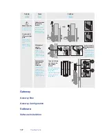
Page 121: ...d fully Square drive was not inserted fully Fireplate F did not correctly align with exterior escutcheon Fireplate F did not correctly align with outside escutcheon Fireplate F did not correctly align with outside escutcheon Square drive must insert through latch and exterior escutcheon Square drive must insert through latch and exterior escutcheon Square drive must insert through latch and exteri...

Page 122: ...nnected Batteries battery holder was not properly connected Batteries battery holder was not properly connected Batteries battery holder was not properly connected Push wire harness in to fully connect pins Push wire harness in to fully connect pins Push wire harness in to fully connect pins F D F Check that batteries and battery holder were correctly inserted Check that batteries were correctly i...

Page 123: ...128 Troubleshoot ...

Page 124: ...Troubleshoot 129 ...

Page 125: ...130 Troubleshoot ...

Page 126: ...Troubleshoot 131 ...

Page 127: ...132 Troubleshoot ...

Page 128: ...Troubleshoot 133 ...

Page 129: ...134 Troubleshoot ...

Page 130: ...Troubleshoot 135 ...

Page 131: ...136 Troubleshoot ...

Page 132: ...Glossary 6 ...

Page 133: ...ata signals from wireless reader locks to from the Host computer guest feature that enables you to add delete cardholders to a lock without reprogramming it host computer computer on which Stanley Intelli M software is installed IP address numeric address like 192 168 1 1 that identifies each device in a TCP IP network issue code access information a credential that allows reuse of the badge ID wh...

Page 134: ...cific range of time may be comprised of several individual intervals timezone defined range of time for various access control activities unlock duration brief period of time the lock is unlocked user individual with a particular access credential wireless lockset lockset which controls access at the door and grants user requests according to how they re configured in Stanley software ...

Page 135: ...140 Glossary ...

Page 136: ...Glossary 141 ...

Page 137: ...142 Glossary ...

Reviews: