


MB656
User
Manual ◄ 21
In its most extreme forms, the combination of surface
damage and severe bending can quickly break even the
best working steels.
The illustrations below show examples of severe stress
breaks.
Figure 20. Severe Stress Breaks
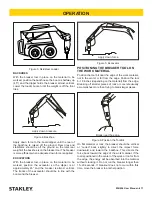
PRYING
This is the most common cause of tool failure. Even
when there is no surface damage, the stress from pry-
ing can easily break a working steel. This kind of failure
generally results from any type of side pressure such as
an incorrect breaking angle or from using the tool to re-
position material. The tool should not be used as a pivot
point when repositioning the carrier. The power gener-
ated by the carrier will far exceed the strength of the tool.
Figure 21. Prying Damage Example
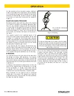
Similar failures can also occur when the steel is used
with extreme down pressure, and the steel repeated-
ly slips off the work at an angle, or the material, itself
moves from under the working steel.
Figure 22. Extreme Down Pressure Breakage
As the next illustration shows, fatigue failures take many
forms, but they all exhibit similar features. Generally, the
broken surface is brittle and has a “lip” like that in the
bending failure, even though, in some cases, the lip has
been broken.
Figure 23. Fatigue Failures
CORROSION
Tools should be greased and stored out of the weather.
Corrosion tends to accelerate the fatigue fractures of the
tool.
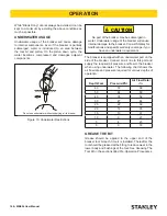
MUSHROOMING
Driving the tool into a hard material for a long period of
time generates an intense heat, indicated by a blue tone
just above the point. This will soften the steel and cause
the point to fold over or mushroom the end of the tool.
Avoid hammering in one location for too long. If material
does not break after a short period (approximately 15 to
20 seconds), reposition the tool.
Figure 24. Mushrooming
If the overheated steel is suddenly cooled by being
dipped in standing water, for example, the metal will
harden and become brittle. These are some examples
of failure caused by temper changes occurring on the
job.
PROPER USE & CARE OF TOOL BITS
Summary of Contents for MB656
Page 29: ...MB656 User Manual 29 MB656 POWER CELL ILLUSTRATION...
Page 33: ......
Page 34: ......
Page 35: ......