Stanley MB656 User Manual Download Page 10

10 ► MB656 

User

 Manual

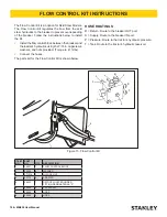
2.  With the carrier at idle and the breaker suspended 

in the air or with minimal down pressure, turn 

on the breaker to gradually warm up its internal 

components.

3.  When the hydraulic system and breaker are warm, 

proceed with operation.

LONG TERM STORAGE

1.  Remove the tool bit. Clean the tool stop and the 

lower bushing. Thoroughly coat the surfaces of the 

tool stop and the lower bushing with grease.

2.  If hoses are attached to the breaker, install plugs 

on the hose ends. If hoses are removed from the 

breaker, install plugs on the hose ends and install 

plugs in the breaker IN and OUT ports.

3.  Store the breaker in a vertical position. Do not store 

the breaker horizontally for extended periods.

OPERATING A BREAKER

PREPARATION FOR USE

Read the section in this manual titled Pre-Operation 

Procedures before operating a breaker. Failure to follow 

the preparation instructions can result in severe damage 

to the breaker and carrier and void the warranties of 

both.

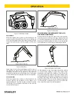
POSITIONING THE CARRIER

SKIDSTEER LOADERS

With the breaker tool in place on the material to be 

worked, position the skidsteer loader arms and the 

breaker bracket so the breaker is almost vertical and the 

front tires of the skidsteer are off of the ground.
Keep lowering the loader arms as the tool penetrates 

the work material so the skidsteer weight stays on the 

tool. The breaker is more efficient when adequate down 

force is applied.

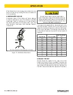
Piston in Down Position

Against Tool Bit

Tool Stop

Lower Bushing

Tool Bit

Tool Bit

Grease Will Fill

This Space

Piston Not Against

Tool Bit Leaving Space

Between the Piston and

Bit

Tool Stop

Lower Bushing

Figure 2. Positioning the Tool Bit with Lubrication

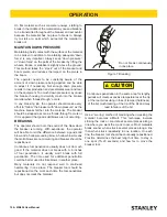
SECURING THE TOOL BIT

1.  The tool retainer is shipped installed in the breaker 

(see parts illustration).

2.  Drive out the tool retainer using a punch and 

hammer.

3.  Grease the top area of the tool bit as shown in 

Figure 1.

4.  Install the tool bit making sure the notch is aligned 

with the lower body retainer pin hole.

5.  Install the tool retainer.

WARNING

Always wear eye protection when installing or 

removing the tool retaining pin.

LOW TEMPERATURE WARM-UP 

PROCEDURE

1.  After starting the carrier, warm-up the hydraulic 

system at engine idle until hydraulic lines are warm 

to the touch.

OPERATION

Summary of Contents for MB656

Page 1: ...2014 Stanley Black Decker Inc New Britain CT 06053 U S A 29169 3 2017 Ver 13 USER MANUAL Safety Operation and Maintenance MB656 MOUNTED HYDRAULIC BREAKER...

Page 2: ...6 kg Has been manufactured in conformity with Wurde hergestellt in bereinstimmung mit Est fabriqu conform ment Ha sido fabricado de acuerdo con E stata costruita in conformit con Directive Standards R...

Page 3: ...OR SERVICE TO THIS TOOL MUST ONLY BE DONE BY AN AUTHORIZED AND CERTIFIED DEALER DECLARATION OF CONFORMITY 2 SAFETY SYMBOLS 4 SAFETY PRECAUTIONS 5 TOOL STICKERS TAGS 8 OPERATION 9 TROUBLESHOOTING 15 M...

Page 4: ...his symbol to avoid possible injury or death DANGER This safety alert and signal word indicate an imminently hazardous situation which if not avoided will result in death or serious injury WARNING Thi...

Page 5: ...when bystanders are in the work area On some machines carriers the breaker can enter the operator s compartment if it breaks loose and swings toward the operator Make sure that suitable impact shield...

Page 6: ...ain conditions must be avoided OBEY SAFETY RULES Operate the breaker in accordance with all laws and regulations which affect you your equipment and the work site Do not operate the breaker until you...

Page 7: ...ervicing to either the carrier or the breaker Do not operate the tool at oil temperatures above 190 F 88 C Operation at higher temperatures can damage the internal components of the breaker and carrie...

Page 8: ...Sticker NITROGEN ONLY 350 PSI 27711 Pressure Spec Sticker 350 psi 74735 CE Specification Plate 74705 Stanley Logo Sticker 47351 Composite Warning Sticker PN 73006 66219 Guaranteed Sound Power Level St...

Page 9: ...lic system to make sure the system is operating at the manufacturers specified capacity and pressure ratings 2 Be sure the fluid in the hydraulic system is filtered to at least 10 micro meters Particl...

Page 10: ...breaker tool in place on the material to be worked position the skidsteer loader arms and the breaker bracket so the breaker is almost vertical and the front tires of the skidsteer are off of the grou...

Page 11: ...of the excavator should be in line with the boom and the breaker Apply down force Figure 5 Excavator POSITIONING THE BREAKER TOOL ON THE WORK MATERIAL Position the tool bit near the edge of the work...

Page 12: ...uld note the sound of the blow when the breaker is running With experience the operator will be able to tell the difference between a good solid blow and a hollow sounding blow A hollow blow means tha...

Page 13: ...The energy is absorbed by the retaining pins other breaker components and the carrier boom components Blank Firing of this type can be experienced in trench work where obtaining striking contact with...

Page 14: ...ill cause internal damage to the breaker Consult Stanley for modifications and specific warranty coverage if you have an underwater requirement The breaker is equipped with an underwater port on the s...

Page 15: ...k Do not pry while operating Breaker runs but at reduced power Low accumulator charge Have unit serviced by an authorized dealer distributor Excessive back pressure Relief set too low Breaker leaks oi...

Page 16: ...l bit Also check for cracks If cracks are present the part must be replaced The extent of wear of the tool stop and lower bushings and the tool bit can be checked by moving a NEW tool bit back and for...

Page 17: ...essure is correct unscrew the gauge to retract the plunger Then loosen and remove the tester from the charge valve If the pressure is not correct proceed to Step 6 NOTE When disengaging the tester a P...

Page 18: ...que to 41 ft lbs Connect the hoses The parts list for the Flow Control Kit is shown below HOSE ROUTINGS R Return Route to the breaker OUT port S Supply Route to the breaker IN port P Pressure Route to...

Page 19: ...pth B 48 in 12 mm Depth RETAINER PIN ITEM 20 2 118 in 53 8 mm Outside Diameter 2 033 in 51 6 mm Outside Diameter RETAINER PIN ITEM 43 75 in 19 mm Outside Diameter 67 in 17 mm Outside Diameter PISTON 2...

Page 20: ...d are used in the most destructive applications Even when the hydraulic breaker is used properly and the operator is an experienced one a tool bit may become damaged When a tool bit has been damaged i...

Page 21: ...er the working steel Figure 22 Extreme Down Pressure Breakage As the next illustration shows fatigue failures take many forms but they all exhibit similar features Generally the broken surface is brit...

Page 22: ...eat Look for surface cracks galling or gouge marks Breaks that start as surface damage have a sea shell pattern with the damaged spot at the center A large sea shell indicates a slow growing break a s...

Page 23: ...hard rock It s pencil type point is used to fracture the material This tool is best where penetration speed is important CHISEL This style of point is used generally used for trench work where a cont...

Page 24: ...is point the pressure reading on the pressure gauge is the back pressure in the circuit This pressure must not exceed 200 psi 13 5 bar Excessive back pressure will slow the attachments operation and l...

Page 25: ...mbient temperature Example Stabilized Temperature 160 Ambient Temperature 80 Heat Rise 80 The normal operating temperature range of this circuit will be the typical ambient temperature range for the g...

Page 26: ...A priority flow control valve manufactured by Stanley Hydraulic Tools Allows for optimum operation of any attachment by providing the proper amount of flow for operation of the tool the priority aspec...

Page 27: ...lb 4131 9000 kg Carrier Size Backhoe 9100 20000 lb 4131 9000 kg TORQUE TABLE Item No Illustration Description Apply Ft Lb Nm 46 Power Cell Hollow Hex Plug 12 SAE Loctite 242 150 203 32 Power Cell Tie...

Page 28: ...er Adapter Assembly 33300 Charge Hose Assembly Includes Valve and Hose for Nitrogen Tank Charge Valve Connections 505232 Charge Kit Assembly Includes P N 505232 28257 and 372047 Charge Kit Box 34892 A...

Page 29: ...MB656 User Manual 29 MB656 POWER CELL ILLUSTRATION...

Page 30: ...P 22 24508 4 O RING 23 24511 1 O RING 24 24512 1 O RING 25 24518 1 O RING 26 27646 1 SYMMETRICAL SEAL 27 27647 1 ROD WIPER 28 27648 1 ROD SEAL 29 27649 1 MODIFIED QUAD RING 30 28128 4 TIE ROD 31 28129...

Page 31: ...I 9 30949 8 HHCS 7 8 9UNC X 3 000 11 47351 1 DECAL COMPOSITE WARNING 13 51255 1 LOWER BUMPER ITEM PART QTY DESCRIPTION 14 51264 1 HOUSING WELDMENT 15 60730 1 POWERCELL BLANK FIRE MB656 16 66219 1 GUAR...

Page 32: ...ting Bracket P N 39056 MB65609 14 Pin Centers Mounting Bracket P N 30913 MB65607 XChange Adapter P N 49309 MB656XC Skidsteer Mounting Bracket P N 56535 Elbow P N 05967 Coupler P N 40092 40093 Adapter...

Page 33: ......

Page 34: ......

Page 35: ......

Page 36: ...Stanley Hydraulic Tools 3810 SE Naef Road Milwaukie Oregon 97267 503 659 5660 Fax 503 652 1780 www stanleyhydraulics com...

Reviews: