background image

CONTROLS 

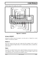
Refer to Figure 6 for location of controls.

Figure 6. Controls

Volume ON/OFF

Rotate the Volume knob clockwise to turn the unit on. Rotate the control
further to increase the volume.

Balance

Grasp the Volume knob and pull it outwards while rotating it left or right to
adjust the speaker left-right balance. The center balance point is indented for
easy location.

Fader

Rotate the concentric Fader knob to adjust the balance between the front and
rear speakers. Rotate clockwise to increase the front speaker volume and
counterclockwise to increase the rear speaker volume.

Page 8                                                            Owner’s Manual                                                            MST65

2813

Summary of Contents for MST65

Page 1: ...MST65 Deluxe AM FM Stereo System Owner s Manual ...

Page 2: ...TION 6 FUSE REPLACEMENT 6 SPEAKER INSTALLATION 7 CONTROLS 8 Volume ON OFF 8 Balance 8 Fader 8 Bass and Treble 9 Loudness LD 9 Liquid Crystal Display LCD 9 Band BND 9 Tuning 9 Manual Station Preset 10 Auto Memory Store AS 10 Preset Scan PS 10 Clock CLK 11 CASSETTE PLAYER 11 Noise Reduction NR 11 Metal Oxide Tapes MT 11 SPECIFICATIONS 12 GENERAL 12 FM RADIO 12 AM RADIO 12 AUDIO AMPLIFIER 12 STEREO C...

Page 3: ... and Treble controls Built in clock automatically displays the time while the cassette is playing or the unit is switched off and at a press of a key when using the radio Automatic Stereo Mono switching and soft muting control Metal tape and tape noise reduction controls Reverse polarity protection of the DC input ACCESSORIES AS101 7 inch Flush Mount Speakers available in black or white AS301 Book...

Page 4: ...noise Often moving as little as 3 feet from your position will correct this problem FM signals travel in straight lines Because the signals are reflected from or absorbed by large solid objects a signal shadow may be present behind the object which may result in poor reception in that area CASSETTE CARE AND MAINTENANCE 1 Tapes no longer than C 90 90 minutes playing time are recommended Avoid using...

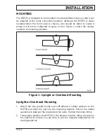
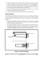
Page 5: ...y or rain Figure 1 shows the various methods of mounting available Figure 1 Upright or Overhead Mounting Upright or Overhead Mounting 1 Attach the two gimbal knobs and self adhesive rubber washers to the MST65 and slide the unit into the mounting bracket Ensure the rubber washers are between the bracket and the radio Tighten the knobs firmly 2 Temporarily position the MST65 in the desired location...

Page 6: ...65 can be neatly flush mounted into a panel or bulkhead so that just the controls and the protective cover are visible There are two flush mounting options available The best option for you will depend on your particular situation If the space behind the bulkhead or panel you have selected has a suitable support shelf and the area is fully accessible you can use the supplied escutcheon panel as de...

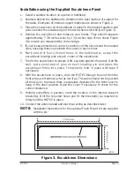
Page 7: ... locating pins at each corner of the escutcheon 7 Trial fit the escutcheon to ensure it fits securely against the panel If all fits well put a small dab of glue on each locating pin and press the escutcheon firmly into place Temporarily hold in place with tape if necessary 8 With the escutcheon in place slide the MST65 through the slot from the front and push it almost as far as it will go The rad...

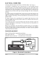
Page 8: ...ory post on the ignition switch On larger vessels with a switchboard the negative lead should go to the common negative bus and the positive lead to the switched and fused radio or spare power circuit The orange fused lead is used to maintain the memories inside the radio and must be connected to a continuous 12 Volt point such as the positive terminal of the battery NOTE It is possible to use the...

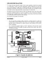
Page 9: ...nting bracket can be mounted in any convenient location Although these speakers have water resistant cones they should be mounted in a sheltered position away from direct spray See Figure 5 for speaker connections WARNING Do not allow the speaker leads even the common lead to come into contact with grounded metal on the vessel or the negative supply If any speaker lead is connected to chassis grou...

Page 10: ...he Volume knob and pull it outwards while rotating it left or right to adjust the speaker left right balance The center balance point is indented for easy location Fader Rotate the concentric Fader knob to adjust the balance between the front and rear speakers Rotate clockwise to increase the front speaker volume and counterclockwise to increase the rear speaker volume Page 8 Owner s Manual MST65 ...

Page 11: ...1 kHz to 1620 kHz The separate FM bands allow stations from different areas to be stored and kept separate Up to 6 channels in each band can be stored in memory making 18 FM and 6 AM channels available e g Hometown FM stations can be stored using FM1 When traveling to new areas new local stations can be located and stored using FM2 or FM3 leaving the hometown stations in FM1 for when you return ho...

Page 12: ...ected band FM1 FM2 or FM3 starting at the currently selected frequency and returning to that frequency when finished The memories for that band will then contain the six strongest FM stations in your area In the AM mode the radio will begin scanning upwards from the currently selected frequency and will store the first six stations found Scanning will then stop Note If the AM stations you wish to ...

Page 13: ...ck the fastforward or rewind keys Press for fastforward and for rewind regardless of which direction the tape is playing To stop fastforward or rewind press the opposite key i e press to cancel etc When the tape reaches the end the unit will automatically reverse the play direction and play the other side of the tape To change the play direction manually press and simultaneously The direction indi...

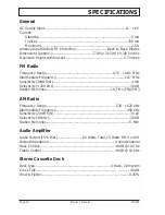
Page 14: ... 10 7 MHz Sensitivity 30dB S N 4 mV Selectivity 200 kHz 30 dB Station Memories 18 FM1 FM2 FM3 AM Radio Frequency Range 530 1620 kHz Intermediate Frequency 450 kHz Sensitivity 20 dB S N 30 µV Selectivity 9 kHz 30 dB Station Memories 6 MW Audio Amplifier Audio Output 10 Dist 60 Watts Total 15 Watts RMS x 4CH Output Impedance 4 ohms channel Bass Control 8 dB 100 Hz Treble Control 8 dB 10 kHz Stereo C...

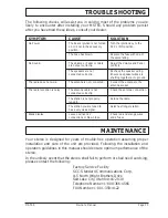
Page 15: ...66 4566 FAX Number 1 801 359 4122 MST65 Owner s Manual Page 13 CAUSE The boat s ignition is not turned on or is not in the accessory position The Fuse has blown The Volume or Fader controls are not set correctly The speakers are not connected correctly The antenna is not connected The antenna cable is not connected correctly The station is not properly tuned in The station you are tuned to has a v...

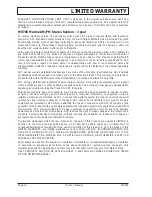
Page 16: ...exceptions exist The purchaser must pay any transportation expenses incurred in returning the Product to SCC for service This limited warranty does not extend to any Product which has been subjected to misuse neglect accident incorrect wiring by anyone other than SCC improper installation or subjected to use in violation of instructions furnished by SCC nor does this warranty extend to Products on...

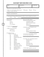
Page 17: ...t Motor Dealer Power Marine Electronics Dealer Commercial Mail Order Other 6 Length of boat ft 10 Why did you choose Standard Horizon 7 Where do you use your boat Features Salt Water Price Fresh Water Recommendation of Dealer Other 8 Equipment on board Now Own Plan to Buy 11 If you hadn t chosen Standard what was Autopilot your next choice indicate brand Desalinator Digital Depth Sounder GPS 12 Ho...

Page 18: ...Standard Communications Corp Attn Advertising Department P O Box 92151 Los Angeles CA 90009 2151 PLACE STAMP HERE Owner s name and address please type or print ...

Page 19: ... warranty repair the Owner s record or other proof of purchase must be included with the unit to provide warranty information THANK YOU for buying Standard Communications products We are confident your new radio will serve your needs for many years OWNER S RECORD Model Serial Number Purchase Date Dealer Owner s Name and Address IMPORTANT Be sure to put this same name and address on the reverse sid...

Page 20: ...Standard Communications Corp P O Box 92151 Los Angeles CA 90009 2151 Telephone 310 532 5300 Standard Communications Corp 1997 All Rights Reserved Printed in Australia September 1997 M32685102A ...

Reviews: