Parameterization and commissioning
14
264707 / 944260310010
2017-12-01·BA00·III·en·00
EN
EN
EN
EN
EN
EN
EN
EN
EN
EN
EN
EN
EN
EN
EN
EN
EN
EN
EN
EN
EN
EN
EN
EN
EN
CPU module for Zone 2
Series 9442/35
7
Parameterization and commissioning
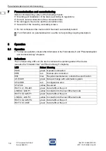
Before commissioning, carry out the following checks:
Mounting and installation of the device according to regulations.
Correct, secure connection of the connection lines.
No damage to the device and the connection lines.
Secure fit of the mounting and safety screws.
Do not commission the device until it has been successfully tested.
8
Operation
8.1
Operation
For device operation, observe the information in the "Intended Use" and "Parameterisation
and Commissioning" chapters.
8.2
Indications
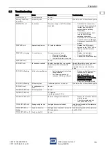
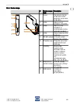
The corresponding LEDs on the device indicate the operating state of the device
(see also the "Intended Use" and "Device Design" chapters).
For information on parameterisation, see the corresponding coupling description.
LED
Colour Meaning
PWR
green Operation indication
ERR
red
Module error indication
M/S
blue
Requires maintenance / outside the specification
AS EXCH
green Data exchange with automation system
CFG ERR
red
Configuration error
STATUS
yellow Reserved
RX/TX X1, RS-485
green Data traffic at the port
LINK X2, LAN P1
yellow Connection to the next Ethernet node
RX/TX X2, LAN P1
green Data traffic at the port
LINK X2, LAN P2
yellow Connection to the next Ethernet node
RX/TX X2, LAN P2
green Data traffic at the port
RX/TX X3, USB
green Data traffic at the port
Summary of Contents for 9442/35-10-00
Page 2: ......


