Mounting and installation
10
264707 / 944260310010
2017-12-01·BA00·III·en·00
EN
EN
EN
EN
EN
EN
EN
EN
EN
EN
EN
EN
EN
EN
EN
EN
EN
EN
EN
EN
EN
EN
EN
EN
EN
CPU module for Zone 2
Series 9442/35
5.4
Redundancy
The IS1+ Remote I/O-System can be redundantly designed based on the application. Here,
a distinction is made between CPU redundancy, power redundancy and system redundancy/
full redundancy.
The following table shows the components required for the respective redundancy concepts:
*System redundancy/full redundancy in preparation
6
Mounting and installation
6.1
Mounting/dismounting
Mount the device carefully and only in accordance with the safety notes
(see "Safety" section).
Read through the following installation conditions and assembly instructions carefully and
follow them precisely.
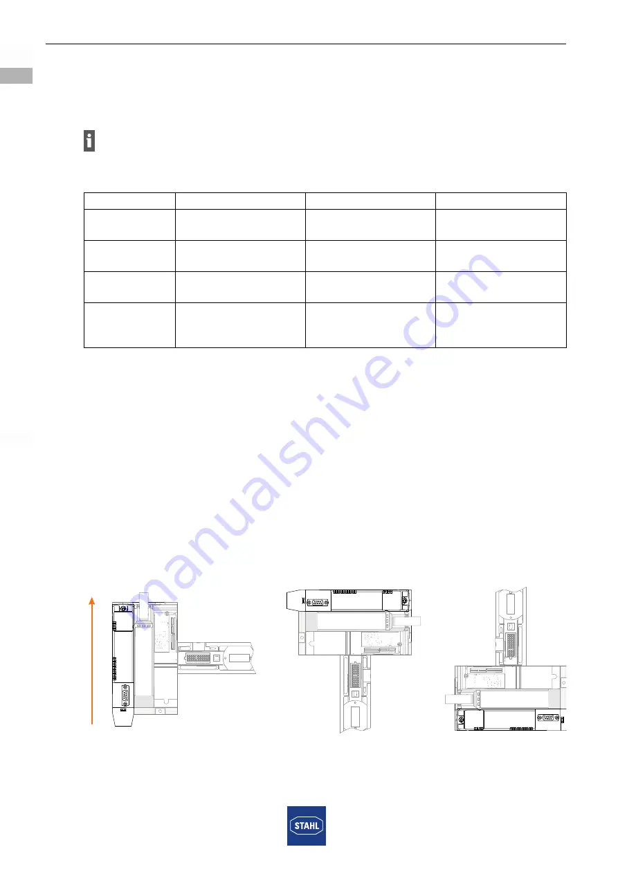
6.1.1 Operating position
Only mount the device (base + connected modules) on the wall:
• Horizontal mounting position with a reading direction from left, or
• Vertical mounting position with an upward or downward reading direction.
Use of a mounting plate is recommended.
19629E00
Comply with the specifications for selecting the suitable 9496/35 base and maximum
equipping of the 9442/35 CPU modules and 9445/35 power modules!
9496/35 base
9442/35 CPU module
9445/35 power modules
No redundancy With 3 slots
1 x CPU
(valid for all protocols)
1 x power module
CPU
redundancy
With 3 slots
2 x CPU (valid for all
protocols)
1 x power module
Power
redundancy
With 3 slots
1 x CPU
(valid for all protocols)
2 x power module
System redun
-
dancy/full
redundancy*
With 4 slots
2 x CPU (valid for all
protocols)
2 x power module
Summary of Contents for 9442/35-10-00
Page 2: ......

