Page | 12
3.
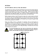
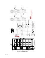
The battery cabinet(s) to be installed must include the at least one –B version.
The first –B cabinet must have its input terminal block (TB1) wired directly to the
UPS. To wire additional battery cabinets, wire from TB2 of the first battery
cabinet to TB1 of the second –B battery cabinet. Repeat these steps for
additional –B cabinets. Use wire sized per local codes, #6 AWG 75°C copper
wire minimum to #3/0 AWG maximum.
When a –N version cabinet is installed with a –B cabinet, the –B cabinet must
have its TB1 terminal block wired to the UPS or another –B cabinet. To wire
from the –B cabinet to the –N cabinet, wire from TB3 of the –B cabinet to TB1 of
the –N cabinet. To wire additional –N battery cabinets, wire from TB2 of the first
–N battery cabinet to TB1 of the second –N battery cabinet. Repeat these steps
for additional -N cabinets.
There must be at least one –B cabinet among the battery cabinets. If it is desired
to create a battery system involving all –N version cabinets and a user provided
disconnect switch, contact Staco for requirements for the disconnect switch.
Please note that a custom configuration of this type is not covered by Staco’s UL
Listing, nor is it covered by this manual.
TB3 is energized at all times. Opening the circuit breakers does not
remove power from this terminal block.
4.
Connect the ground wire to the ¼-20 ground stud with a ring terminal or pressure
lug by removing and replacing the top nut and washers only with a 7/16” wrench.
5.
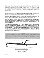
Before working within the UPS cabinet, verify that the UPS has no power applied.
Before touching the Extended Run Time Battery connector in the UPS, verify that
all internal battery strings are disconnected (that is, verify that the blue and white
“powerpole” connectors are NOT mated). Refer to the UPS manual. Repeat
procedures 3 and 4 to the FirstLine PL UPS Extended Run Time Battery
connector located in the lower left side of the UPS. We recommend that the wires
be marked as to which is positive (+) and negative (-) to ensure that the wires are
not accidentally crossed. See
Figure 9
.
Never connect the positive to the negative. Severe damage and injury
could result. Check polarity at the TB3 terminal block.
6.
For –B cabinets, connect the Circuit Breaker Interface per Section 5.
7.
Mate the blue connections, blue to blue, and then the white connections, white to
white. See
Figure 9
. Repeat this procedure for the other battery cabinets, if
present.
8.
Reinstall the front inner panel on each battery cabinet using the screws provided.


