Page | 8
10.
Carefully move the cabinet to the desired location and slowly lower the cabinet to
the floor or other appropriate flat surface. Bolt to the floor if desired.
11.
With a Phillips screwdriver mount the four kick panels that were wrapped and
placed in the cabinet.
SECTION 4
ELECTRICAL INSTALLATION
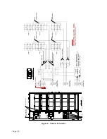
The FirstLine PL Extended Run Time Battery Cabinet has the following power
connections:
TB1, 3 pole (positive, neutral, negative) terminal block and ground connection for
battery power input. This goes to the UPS or to the next battery cabinet closer to
the UPS.
TB2, 3 pole (positive, neutral, negative) terminal block and ground connection for
battery power output. This goes to the input of the next battery cabinet in the set.
TB3, 3 pole (positive, neutral, negative) terminal block and ground connection for
battery power output. This goes to the input of the –N version battery cabinet
from the first –B version battery cabinet closest to the UPS.
TB3 is energized at all times. Opening the circuit breakers does not
remove power from this terminal block.
Only qualified service personnel (such as a licensed electrician) should
perform the UPS installation and initial startup. Risk of electrical shock.
WIRING PREPARATION
To begin wiring the UPS:
1. Verify that the electrical connections to the installation site have been properly
installed.
2. A wall-mounted, user-supplied, readily-accessible disconnection device must be
incorporated in the battery input wiring unless at least one of the battery
cabinets is a –B version.
3. Wire the FirstLine PL/PLT UPS per the User’s Handbook.
WARNING


