background image

12

Pump Reassembly/Installing New Seal

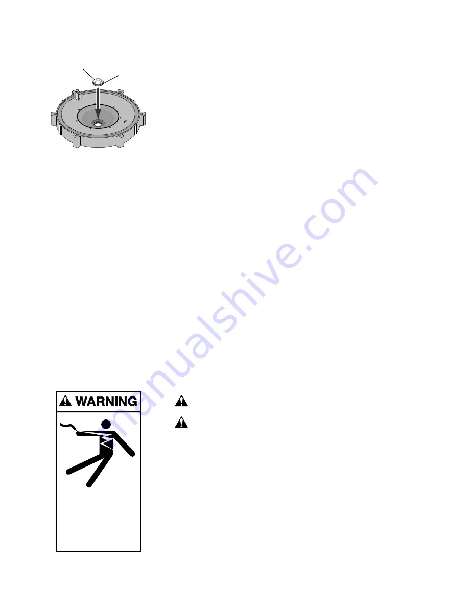
1. Ceramic seat must be clean and free of dirt, grease, dust, etc. Wet outer

edge with small amount of liquid detergent; press ceramic seat into seal
plate cavity firmly and squarely with finger pressure (Fig. 8).

2. If ceramic seat will not locate properly, remove it, place 

face up 

on bench

and reclean cavity. Ceramic seat should now locate.

3. If seat still will not locate properly, place a cardboard washer over the

polished face and use a piece of 3/4" (19mm) standard pipe for pressing
purposes. 

NOTICE: Be sure 

not to scratch or mar polished surface or seal

will leak.

4. Replace slinger on end of motor shaft so that impeller sleeve will push it

into position. If slinger shows signs of wear or damage, replace it.

5. Remount seal plate on motor. Tighten bolts to 60-80 inch-lbs. (69-92

kg/cm) torque.

6. Apply a 

small 

amount of liquid detergent to inside diameter of rotating

half of seal.

7. Slide rotating seal member, polished carbon face out, over impeller sleeve

until rubber drive ring hits back of impeller.

NOTICE: Be sure 

not to nick or scratch polished seal face; seal will leak if

face is damaged.

8. Screw impeller onto shaft (clockwise); this will automatically locate seal in

seal plate.

NOTICE:

On 2 and 2-1/2 HP models; install impeller gasket and lock

screw (left-hand thread - turn counterclockwise). Torque lock screw to
50-55 inch-lbs. (57.6-63 kg/cm).

9. Mount diffuser on seal plate; tighten screws to 10-14 inch-lbs. (11.2-16.1

kg/cm) torque.

10. Assemble motor and seal plate to pump body with nuts, flat washers and

lock washers. Torque nuts to 120-130 in-lbs. (138-150 kg/cm).

11. Prime pump according to instructions on Page 9.

TROUBLESHOOTING GUIDE

Read and understand safety and operating instructions in this manual

before doing any work on pump!

Only qualified personnel should electrically test pump motor!

FAILURE TO PUMP; REDUCED CAPACITY OR DISCHARGE PRESSURE

Suction leaks/lost prime:

1. Pump must be primed; make sure that pump volute and trap are full of

water. See priming instructions, Page 9.

2. Make sure there are no leaks in suction piping.
3. Make sure suction pipe inlet is well below the water level to prevent

pump from sucking air.

4. If suction trap gasket is defective, replace it.
5. Make sure pump is not trying to lift water more than 10'(3m).
6. Make sure suction pipe is at least 2" (51mm) in diameter.

Polished

surface

Rubber

surface

Hazardous voltage.
Can shock, burn,
or cause death.

Disconnect power
before working
on pump or motor.

Figure 8

Summary of Contents for DYNA-GLAS

Page 1: ...3115 North America 800 752 0183 FAX 800 582 2217 International 262 728 5551 FAX 262 728 4461 TELEX ITT 4970245 www sta ritepool com Union City TN Delavan WI Mississauga Ont Murrieta CA Printed in U S...

Page 2: ...3 Installation 4 5 Pool Pump Suction Requirements 5 6 Electrical 7 8 Operation 9 Storage Winterizing 9 10 Pump Service 11 12 Troubleshooting Guide 12 13 Repair Parts List 14 15 Warranty 16 Single Spee...

Page 3: ...BE SURE all air is out of system before operating or testing equipment Before pressure testing make the following safety checks Check all clamps bolts lids and system accessories before testing Releas...

Page 4: ...piping Fire and burn hazard Modern motors run at high temperatures To reduce the risk of fire do not allow leaves debris or foreign matter to col lect around the pump motor To avoid burns when handli...

Page 5: ...low for a pump installation which minimizes risk to users of pools spas and hot tubs Entrapment Protection The pump suction system must provide protection against the hazard of suction entrapment or h...

Page 6: ...tions Testing and Certification Suction outlet covers must have been tested by a nationally recognized testing laboratory and found to comply with the latest ASME ANSI Specifications for Suction Fitti...

Page 7: ...g wire to the pressure wire connector provided on the motor housing and to all metal parts of the swimming pool spa or hot tub and to all electrical equipment metal piping or conduit within 5 feet 1 5...

Page 8: ...2 1 2 15 11 9 3 5 230 60 1 14 2 14 2 12 3 2 15 10 4 230 60 1 14 2 14 2 12 3 2 1 2 15 11 2 230 60 1 14 2 14 2 12 3 MPFA SERIES SINGLE SPEED 3 4 15 15 9 9 5 0 115 230 60 1 14 14 2 2 10 14 5 5 2 10 14 5...

Page 9: ...ate the trap cover O Ring The original equipment O Ring con tains a permanent internal lubricant NOTICE If you replace the O Ring with a non internally lubricated O Ring you may need to apply a silico...

Page 10: ...ezing remove trap cover and drain the tank body through the two drain plugs provided A Gravity drain system as far as possible B Protect areas which retain water with non toxic propylene glycol antifr...

Page 11: ...e in trap body remove cover unscrew by turn ing counterclockwise 3 Remove 6 nuts lockwashers and flat washers holding seal plate to pump body Pull seal plate and motor away from pump body You may have...

Page 12: ...impeller onto shaft clockwise this will automatically locate seal in seal plate NOTICE On 2 and 2 1 2 HP models install impeller gasket and lock screw left hand thread turn counterclockwise Torque lo...

Page 13: ...ay be running too slowly check voltage at motor terminals and at meter while pump is running If low see wiring instructions or consult power company Check for loose connections 11 Pump may be too hot...

Page 14: ...148L 1 1 2 AE100FLL MPFA6D 176L 3 4 A100DLL MPFA6E 146L 1 A100ELL MPFA6F 147L 1 1 2 A100FLL 230 60 1 MPRA6G 155L 2 A100GLL MPEA6G 155L 2 AE100GLL MPEAA6G 168L 2 1 2 AE100G5LL Two Speed 230 60 1 MPRA6Y...

Page 15: ...Ring 1 U9 375 U9 375 U9 375 U9 375 U9 375 14 Trap Basket 1 C8 58P C8 58P C8 58P C8 58P C8 58P 15A Drain Plug 2 U178 920P U178 920P U178 920P U178 920P U178 920P 15B Mounting Screw 5 16 14x5 8 2 U30 9...

Page 16: ...pur chaser Purchaser only Sta Rite shall have the option to re pair or replace the defective product at its sole discre tion Purchasers must pay all labor and shipping charges nec essary to replace t...

Reviews: