


To reduce risk of electric shock, pull
plug before servicing. This pump has not been inves-
tigated for use in swimming pool areas. Pump is sup-
plied with a grounding conductor and grounding-type
attachment plug. Be sure it is connected only to a
properly grounded grounding-type receptacle.
Where a 2-prong wall receptacle is encountered, it
must be replaced with a properly grounded 3-prong
receptacle installed in accordance with codes and
ordinances that apply.
12. A ground fault circuit is recommended for use with any
electrical appliance submerged in water. Installation and
all wiring should be performed by a qualified electrician.
13. Make certain power source conforms to requirements of
your equipment.
14. Protect electrical cord from sharp objects, hot surfaces,
oil, and chemicals. Avoid kinking cord. Replace or repair
damaged or worn cords immediately.
15. Do not touch an operating motor. Modern motors are
designed to operate at high temperatures.
16. Do not handle pump or pump motor with wet hands or
when standing on wet or damp surface, or in water.
Risk of electric shock. If your basement has
water or moisture on floor, do not walk on wet area until all
power has been turned off. If shut-off box is in basement,
call electric company or hydro authority to shut-off service
to house, or call your local fire department for instructions.
Failure to follow this warning can result in fatal electrical
shock.
Remove pump and repair or replace.
DESCRIPTION
This Submersible Sump Pump is designed for home sumps.
Unit is equipped with a 3-prong grounding-type power cord. The
shaded-pole motor is oil filled and sealed for cooler running.
The sleeve bearings on the motor shaft never need lubrication.
The pump includes automatic reset thermal protection.
Pump water only with this pump.
SPECIFICATIONS
Power supply required . . . . . . . . . . . . . . . . . . . .115V, 60 HZ
Liquid Temp. Range . . . . . . . . . . . . . . .32°F-70°F (0°-21°C)
Individual Branch Circuit Required . . . . . . . . . . . . .15 Amps
Discharge Adapter* . . . . . . . . . . . . . . . . . . . . . .1-1/2” FNPT
* D175 Series Models have a 1-1/2” Slip Discharge Pipe Size
and a 77°F Maximum Temperature.
NOTE:
Do not use where fish are present. Any leakage of oil
from the motor into the water can kill fish.
Not for use where water recirculates.
Not designed for use as a swimming pool drainer.
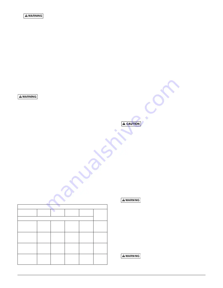
PERFORMANCE
INSTALLATION
1.
Install pump in sump pit with minimum diameter of 10"
(254mm) for models equipped with vertical switches
and 14" (356mm) for float switch models. Sump depth
should be 14" (356mm). Construct sump pit of tile, concrete,
steel or plastic. Check local codes for approved materials.
2.
Install pump in pit so that switch operating mechanism
has maximum possible clearance.
3.
Pump should not be installed on clay, earth or sand sur-
faces. Clean sump pit of small stones and gravel which
could clog pump. Keep pump inlet screen clear.
NOTICE:
Do not use ordinary pipe joint compound on
plastic pipe. Pipe joint compound can attack plastics.
4.
Install discharge plumbing. When using rigid pipe, use
plastic pipe.
A. For D125, D133, and D150 Series: Wrap thread
with Teflon tape
TM
. Screw pipe into pump hand tight +1
– 1-1/2 turns. Thread outlet pipe into pump body
carefully to avoid stripping or crossing threads.
B. D175 Series: Slip connector hose over pump dis-
charge. Install and tighten first clamp. Place second
clamp loosely over connector hose. Slip connector
hose over discharge pipe. Clamp hose tightly with
second clamp.
NOTICE:
Discharge piping should be as short as possi-
ble to reduce pipe friction losses. Discharge
pipe diameter should be equal to or larger than dis-
charge size of pump. Smaller pipe diameters will restrict
capacity of pump and reduce performance. Do no use
flexible discharge pipe in any permanent installation.
Risk of flooding. Failure to secure
pump may allow pump movement, switch interfer-
ence and prevent pump from starting or stopping.
If a flexible discharge hose is used, make sure pump is
secured in sump to prevent movement.
5.
To reduce motor noise and vibrations, a short length of
rubber hose (e.g. radiator hose) can be connected into
discharge line near pump using suitable clamps.
6.
For D125, D133, and D150 Series ONLY: Install an in-
line check valve to prevent flow backwards through pump
when pump shuts off.
NOTICE:
Drill 1/8" (3.2 mm) hole in discharge pipe just above
pump body but below check valve to prevent air locks. D175
Series pumps have an internal check valve and don’t
require drilling.
7.
Power Supply: Pump is designed for 115 V., 60 Hz., opera-
tion and requires a minimum 15 amp individual branch cir-
cuit. Both pump and switch are supplied with 3-wire cord
sets with grounding-type plugs. Switch plug is inserted
directly into outlet and pump plug inserts into opposite end
of switch plug.
Hazardous voltage. Pump should always
be electrically grounded to a suitable electrical ground
such as a grounded water pipe or a properly grounded
metallic raceway or ground wire system. Do not modi-
fy cord or plug or cut off round ground pin.
8.
Secure discharge line before starting pump.
9.
If pump discharge line is exposed to outside sub-freezing
atmosphere, portion of line exposed must be installed so
any water remaining in pipe will drain to the outfall by
gravity. Failure to do this can cause water trapped in dis-
charge to freeze which could result in damage to pump.
10. After piping and check valve (if needed) have been
installed, unit is ready for operation.
11. Check operation by filling sump with water and observing
pump operation through one complete cycle.
Failure to make this operational check
may lead to flooding and premature failure.
NOTICE:
This unit is not designed for applications involving salt
water or brine! Use with salt water or brine will void warranty.
TM
E.I. DuPont De Nemours and Company Corporation, Delaware.
2
GPM (LPM) AT TOTAL FEET (m)
5
10
15
20
Model
(1.5m)
(3m)
(4.6m)
(6.1m)
CAPACITY GALLONS(L)/MINUTE
D12518T
38
30
14
–
18 Ft.
D12518V
D125115T
(144) (114)
(53)
(–)
(5.5m)
D13318T
46
36
24
0
20 Ft.
D13318V
D133115T
(174) (136)
(91)
(0)
(6.1m)
D15018T
54
45
33
20
24 Ft.
D15018V
D150115T
(204) (170)
(125)
(76)
(7.3m)
D175110T
85
70
50
30
27 Ft.
D175120M
D175120V
(322) (265)
(190)
(114)
(8.2m)
No flow
at height
shown
below


