4
English
Mounting
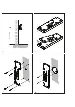
marking).
4
When mounting on a switch box,
use the screw openings in the centre
of the device, paying attention that
the plate is the right way up (top
marking).
5
Install in accordance with the
AS diagram. The cores of the
installation cable must be stored
inside the free installation space in
the base plate.
6
Insert the coloured plug of the
spiral cable into the socket at the
housing. A distinct click is audible
when the plug is correctly inserted.
7
Insert the other end of the
spiral cord in the receiver until
the plug audibly clicks into place.
This connection can no longer be
detached.
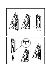
8
Hook the top of the housing into
the base plate and close by exerting
a slight pressure.
Dismantling
9
To remove the housing, press
the lock upwards using a flat blade
screwdriver. The circuit board and
receiver remain on the upper part of
the housing.
Terminal assignment
TaM/TbM = In-home bus input
TaM/TbM = In-home bus
throughput
ERT/ETb = Storey call button
+M/-M = additional supply
20 - 30 V DC
S1/S1
= potential-free contact
for extra doorbell
15 V AC, 30V DC, 1A
Commissioning
Installation and commissioning
procedures are described in the
system manual (enclosed with Bus
Video Line Rectifier BVNG 650-…).
Note
As in the as-delivered / de-energized
status, the contact position of
the bistable relay (contact S1/S1)
cannot be defined, the bus supply
to the device must be connected
beforehand to ensure that the
bistable relay functions correctly.
Standard bus telephone with
colour monitor
for Siedle in-home bus
Functions:
• Calling, speech, vision, door
release and storey call
• Colour monitor 6.3 cm (2.5 “)
• Door opener and light button
• Mute button for call tone
• 11 call tone melodies
• Monitor button for current picture
• Brightness and colour regulation
Electrical voltage
Mounting, installation and
servicing work on electrical
devices may only be performed
by a suitably qualified electrician.
Electrostatic charging
As a result of electrostatic charging,
direct contact with the circuit
board can result in destruction of
the device. Direct contact with the
circuit board must therefore be
avoided.
Scope of supply
• BTSV 850-… (base plate and
housing with monitor unit)
• Receiver
• Spiral cable
•
Operating instructions for the
end user
• This product information
Mounting
Strip the cable back to 80 mm.
1
Recommended mounting height
appr. 1.50 m to centre device.
2
Open the device from the back by
pressing in the locking lever.
3
When mounting directly on the
wall, fasten the base plate using
4 screws, paying attention that
the plate is the right way up (top
Accessories for BTSV 850-…
• ZTSV 850-… for conversion from a
wall appliance to a table appliance.
Specifications
• Supply via in-home bus
• Ring tone volume: max. 83 dB (A)
• Colour monitor 6.3 cm (2.5 “)
• Current consumption on supply via
+M/-M max. 300 mA
• Potential-free contact S1/S1
max. 15 V AC, 30V DC, 1A
Switching time 0.4 secs. - 19 mins.
• Dimensions W x H x D
90 x 261 x 45 mm
Summary of Contents for BTSV 850-02
Page 2: ...8 9 ...
Page 3: ...1 3 4 2 ...
Page 4: ... 2 6 7 5 ...
Page 12: ... 10 ...
Page 13: ... 11 ...


