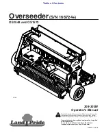
background image

1009510 Rev A

13

D

C

A

B

E

Level

6.  Push the LH side (A) of the bracket pulley down and 

tighten the LH nut (B) slightly to hold the bracket at an 
angle.

7.  Using a small crow bar reach in from the rear and 

pull up on the crow bar to push down on the bracket 
pulley until the transmission drive belt (C) is level with 
the transmission sheave (D), tighten up the RH nut (E) 
completely.

8.  Tighten the 5/16 hex nuts (B,E).
9.  Check Transmission belt (C) for tension.  There should 

be 3/16 in. defl ection when belt is pushed by hand.

10. Replace both safety covers.

B. Replacing Slicer Drive Belt

1.  Ensure that the engine is off.
2.  Disconnect the spark plug.
3.  Ensure that the rear wheels are chocked.
4.  Ensure that the slicer control lever is not engaged.

A

A

B

A

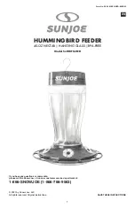
5.  Remove hex bolts (A) retaining left side belt cover (B) 

and remove cover (B).

A

B

Hex bolt on other 
side of Tensioner.

6.  Loosen hex bolt retaining tensioner (B) to remove belt 

tension.

7.  Remove slicer drive belt (A) from pulley and engine 

sheave.

8.  Install replacement belt (A) on pulley and engine 

sheave.  

NOTE:

 Install idler pulley on inside of belt, as 

shown.

9.  Turn bolt on tensioner until tensioner (B) is set at the 

4th tick mark, and re tighten the hex bolt. 

10. Re-install the belt cover.

Summary of Contents for S120-4510

Page 1: ...ders Contact Us at 800 972 6130 This manual contains information for the safety of persons and property Read it carefully before assembly and operation of the equipment IMPORTANT Model S120 4510 Powered Seeder Operator s Manual ...

Page 2: ...ents approved by the manufacturer 2 Wear appropriate clothing including safety glasses hearing protection long pants and safety shoes Long hair loose clothing or jewelry may get tangled in moving parts 3 Inspect the area where the equipment is to be used and remove all objects such as rocks toys and wire which can be thrown by the machine 4 Use extra care when handling gasoline and other fuels The...

Page 3: ...ly replace slicer blades Never straighten or weld them 11 Keep hands and feet away from moving parts If possible do not make adjustments with the engine running 12 Keep all parts in good working condition and all hardware tightened Replace all worn or damaged decals SPECIFICATIONS Engine Honda GX270 recoil start Traction Drive Hydro Gear transaxle Maximum Forward Speed 0 2 mph variable Slicer Reel...

Page 4: ...ury keep hands and feet away from rotating blades To avoid injury do not operate machine without safety shields in place WARNING ADVERTENCIA Para evitar las lesiones no opere la máquina sin las cubiertas de seguridad colocadas 1009412 WARNING To avoid injury do not operate machine without safety shields in place CAUTION To avoid injury keep fingers away from the clevis pin on the slicer blade dept...

Page 5: ... between 1 4 in above ground to 1 in into ground 6 Free Wheel Lever BYPASS FREE WHEEL DESVÍO RUEDA LIBRE OPERATION DRIVE OPERACIÓN ACCIONAMIENTO Controls Bypass free wheel and Operation drive functions of the trans axle Push in and down for Bypass Pull out and down for Operation 7 Parking Brake Lever Pull up to release parking brake Pull out and down to engage parking brake Forward Ground Speed Co...

Page 6: ... To start the engine ensure both levers are in their neutral position Forward motion is variable based on where the lever is positioned in the forward mode To operate the unit in reverse the reverse lever must be held 10 Seed Flow Lever Move the lever forward to open the seed plate allowing seeds to flow through the openings Move the lever to the rear to stop seed flow To close the hopper gate pla...

Page 7: ... Operate all controls until operator is familiar with every control and motion of the unit C Safety Systems Test The safety systems installed on your unit should be checked before each use Read the operator manual and be completely familiar with the operation of the unit before performing these checks Use the following procedures to check for normal operation If there is a malfunction during one o...

Page 8: ...Injury Always ensure that slicer blades have come to a complete stop before leaving operator s position B SHUT OFF 1 Release slicer blade control lever and wait for slicer blades to stop rotation 2 Move throttle lever to slow setting and allow engine to return to idle 3 Move engine switch to OFF position 4 Move the fuel shutoff valve to the OFF position F Moving Forward and Backward A TO MOVE UNIT...

Page 9: ... Danger Avoid Injury Always ensure that slicer blades have come to a complete stop before leaving operator s position A TO ADJUST THE SLICER DEPTH 1 Move seed flow control lever to OFF position 2 Disengage slicer control lever and wait for slicer blades to stop rotating 3 Place Ground Speed Lever in neutral A B C 4 Move the slicer depth locator pin A to the desired location 5 Squeeze the lock hand...

Page 10: ...enovating an area surrounded by walkways or driveways make at least two complete passes around the perimeter This will provide enough room to make turns at the end of each pass without the slicer blades contacting concrete or asphalt MAINTENANCE AND STORAGE Warning Avoid Injury Disconnect the spark plug before performing any maintenance A General Maintenance 1 Refer to the engine owner s manual fu...

Page 11: ...area 2 LONG TERM Clean unit thoroughly with mild soap and low pressure water and lubricate Touch up all scratched painted surfaces Remove weight from wheels by putting blocks under frame or axle Inspect all parts for rust and replace if necessary 3 FUEL SYSTEM NOTE Gasoline left in the fuel system for extended periods without a stabilizer will deteriorate resulting in gum deposits in the system Th...

Page 12: ...A Tightening the Transmission Belt After 8 Hr A 1 Turn off engine and ensure that the spark plug A is disconnected 2 Chock rear wheels A A B A 3 Remove six hex bolts A retaining left side belt cover B and remove cover B A B 4 Remove the four hex bolts A that retain the rear maintenance cover B A 5 Loosen the 5 16 in hex nuts A holding the bracket pulley to remove belt tension ...

Page 13: ...hand 10 Replace both safety covers B Replacing Slicer Drive Belt 1 Ensure that the engine is off 2 Disconnect the spark plug 3 Ensure that the rear wheels are chocked 4 Ensure that the slicer control lever is not engaged A A B A 5 Remove hex bolts A retaining left side belt cover B and remove cover B A B Hex bolt on other side of Tensioner 6 Loosen hex bolt retaining tensioner B to remove belt ten...

Page 14: ...so that slack is removed from the cable without beginning to move the clutch brake arm 4 Tighten cable bracket nuts B 5 Re install pulley guard D Replacing Slicer Blades Every 2 yr 1 Ensure that the engine is off 2 Disconnect spark plug 3 Ensure that the slicer control lever is not engaged 4 Ensure that the rear wheels are chocked 5 Raise the front or Hopper end up on jack stands no higher than 8 ...

Page 15: ...m the pulley III Remove the bushing and pulley from the shaft NOTE The shaft has a key at the end where the pulley is assembled which may come out when you remove the pulley In the event that this happens please take care not to lose the key The slicer blades will not turn without the key Loosen and remove bolts on both sides 10 Remove the 1 2 hex bolts and 1 2 hex nuts that attach bearings to eng...

Page 16: ...from the Previous One 18 Place new blade I with cutting edge facing forward as shown on axle H along with the spacer 19 Replace all the blades I and spacers J making sure to stagger the blade orientation for every other blade 20 At the non threaded end of the axle H replace K L and A 21 At the threaded end of the axle H replace F as shown Ensure that small spacer F is protruding out from square ax...

Page 17: ...re that the bolts are evenly tightened Turn one bolt a quarter of a turn into the pulley and then move to the next bolt and tighten the same amount Keep alternating between bolts when tightening until the bushing is completely tightened to the pulley NOTE As it becomes more difficult to tighten the bolts reduce the amount of turning that is applied to each bolt as you alternate Apply thread locker...

Page 18: ...and remove it from the clutch brake B Allow the transmission belt G to fall below the engine output shaft H 11 Remove clutch brake B A B 12 Remove 4 bolts that retain the rear maintenance cover To replace the transmission belt follow steps 13 to 26 To replace the clutch brake pulley proceed to step 15 Replace A B C D 13 Un wrap transmission belt B from mule drive C and transmission B 14 Replace ne...

Page 19: ...at was removed previously Reinstall 18 Reinstall the 1 4 carriage bolt and nut that were removed previously between clutch brake lever and bracket D C A B E Level 19 Push the LH side A of the bracket pulley down and tighten the LH nut B slightly to hold the bracket at an angle 20 Using a small crow bar reach in from the rear and pull up on the crow bar to push down on the bracket pulley until the ...

Page 20: ...e left rod adjusts reverse speed and the right rod adjusts the forward speed The two rods can be adjusted independently 3 Re tighten 5 16 nuts A when you are finished adjusting the ground speed 4 The material calibration chart on this machine assumes a ground speed of 2 mph is used If ground speed is changed the material flow rate needs to be recalibrated TROUBLESHOOTING Symptom Possible Cause Sol...

Page 21: ...ll not be liable for any loss damage or expense including but not limited to consequential or incidental damages arising from the operation condition or use of the item The sole and exclusive remedy against Spyker Spreaders being the replacement of the defective parts This warranty gives you specific legal rights and you may also have other rights which vary from state to state This express warran...

Reviews: