13
field repair
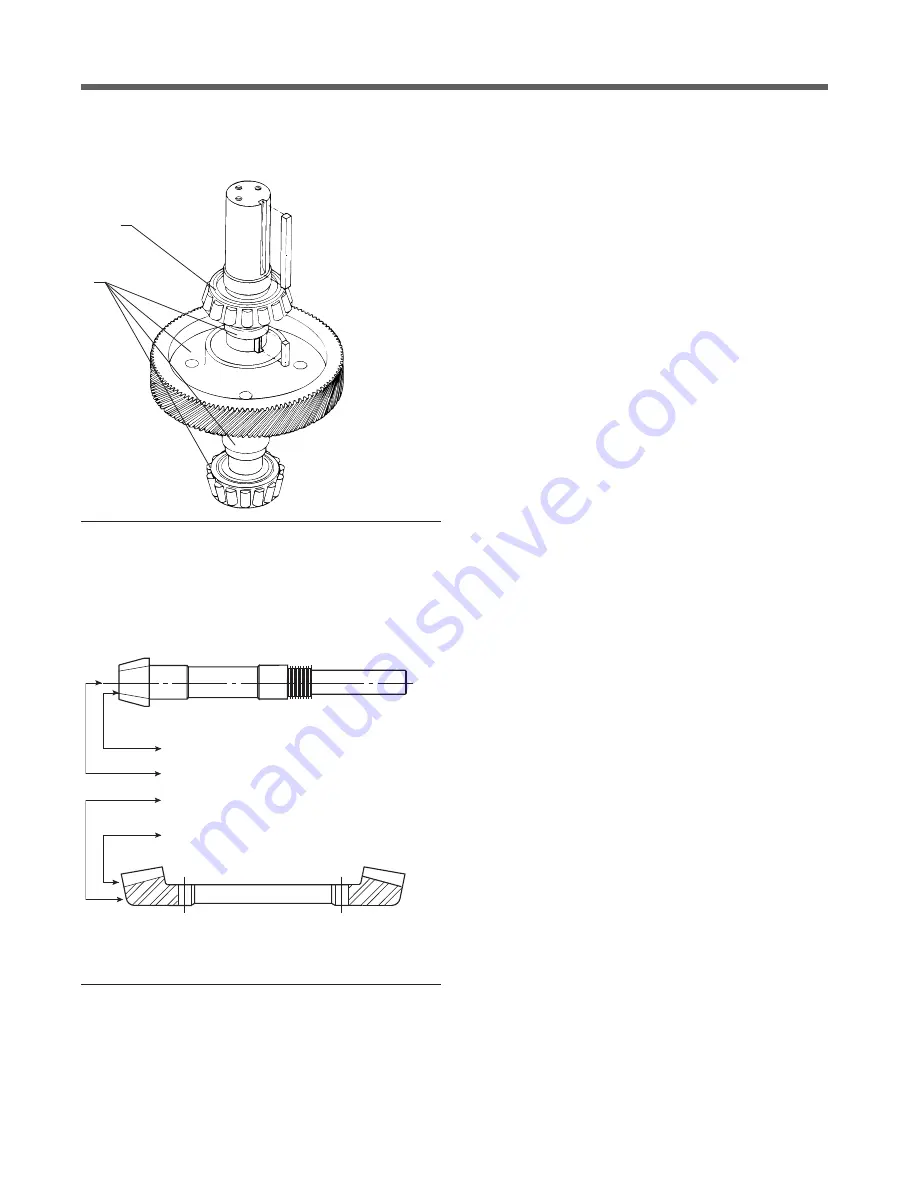
Figure 10
Gear Match Numbers and Setting Data
MATCHED NUMBER TO BE COMPARED WITH THE SAME
NUMBER ON THE RING GEAR. (EXAMPLE CO-43)
PINION SETTING DISTANCE. (EXAMPLE 4.860)
BACKLASH (NORMAL) AT WHICH THE GEARS WERE
LAPPED. (EXAMPLE .010)
MATCHED NUMBER TO BE COMPARED WITH THE SAME
NUMBER ON THE PINION GEAR. (EXAMPLE C0-43)
THE PINION SETTING DISTANCE IS THE DISTANCE
THE END OF THE PINION SHOULD BE FROM THE
CENTERLINE OF THE RING GEAR SHAFT.
Figure 9
Disassembly of Fan Shaft
Disassembly of Fan Shaft
Part numbers and references—refer to
Figures 3, 4 and 9
.
1. Press helical ring gear (201), lower fan shaft spacer (40)
and lower cone (421) from shaft. Remove key spacer ring.
2. Remove upper bearing cone (422)and water slinger spacer
(703).
3. Remove upper fan shaft bearing cup (422) from case cover
(not illustrated).
4. Remove lower fan shaft bearing cup (421) from case (not
illustrated).
Assembly of Geareducer
Gear Match Numbers and Setting Data
Before assembling a new pinion gear in the pinion cage, check
match numbers on pinion gear and spiral bevel ring gear to be
certain they are a matched set. Gears are lapped in matched sets
at the factory and should not be separated. Numbers are etched
on both the pinion and ring gear as illustrated in Figure 10.
Pinion Cage Assembly
Part numbers and references—refer to
Figures 3, 4 and 11.
1. Press oil slinger (102) onto pinion shaft.
2. Install pinion head bearing cone (402) on pinion shaft.
3. Press pinion head bearing cup (402) into pinion cage.
4. Press pinion tail bearing cup (401) into pinion cage.
5. Lower pinion cage over pinion shaft until head bearing cone
(402) mates with cup.
6. Press tail bearing cone (401) onto pinion shaft.
a–Lock with lock nuts (103) and lockwasher (104) to pro-
vide bearing preload of 10 to 18 in·lbƒ (1130-2034 mN·m)
resistance to rotation of pinion shaft.
b–Crimp ears of lockwasher (104) to locknuts after obtaining
prober preload.
7. Model 3400. Slide oil seal (701) onto pinion shaft. Model
34.4. Press oil seal (701) in pinion cage cap.
8. Assemble pinion cage cap to pinion cage with gasket (601)
or RTV. Tighten bolts (23) to 55 ft·lbƒ (75 N·m) torque.
Model 3400. Make sure rotating seal member magnetically
engages stationary element in cap.
1
2


