21
6.5 NOZZLE CONFIGURATION
1.
Start with the nozzle body slide all the way down to the end blocks and with the ground rods moved as far out
from the nozzle body as possible.
2.
Position the manifold so that nozzle spray tube tips are
8”
above the target with tubes pointing straight down.
3.
Allow enough time for fluid to start dripping from every orifice before applying voltage.
4.
Start the voltage at zero and slowly increase, watch for when the drops start to form into small cones. These
small cones will have a series of single file droplets propelling off from the tip. At the lower end of the voltage
range, droplets will be heavier with spaces in between. As voltage is increased, droplets will shrink and appear to
be one very thin, continuous stream.
ADJUSTMENT OF SPRAY DISTRIBUTION
If the spray pattern appears
“
streaky
”
or has heavy drops, try one or all of these:
•
Increase voltage
•
Move the ground rods in closer to the nozzle tips
•
Increase the distance between the manifold and the target. This will give the droplets more time in the air, which
allows for more atomization, so the drops can break up and spread out evenly.
If the spray is extremely fine and droplets appear to be floating away, try one or both of these:
•
Lower voltage
•
Position the Manifold closer to the target
Note:
The spray produced by the manifold can be very faint and hard to see. Using a flashlight to illuminate the spray
distribution from different angles may be necessary for pattern identification.
6.6 START
-
UP PROCEDURE
1.
Verify that all system electrical and liquid connections are properly connected and secure.
2.
Ensure that the manifold is plumbed and positioned properly above the target.
3.
Verify that the manifold grounding wires are properly connected. (Ensure that it is plugged into a GFCI outlet)
4.
Fill the tank with fluid. Always check the tank level sensor reading or visually confirm that there is enough fluid in
the tank before spraying.
5.
Look to the strainer valve assemblies on the fluid delivery cart. Ensure that the one strainer assembly has the
inlet and outlet valves in the open position, and that the other strainer has the inlet valve open. Keep the second
strainer outlet valve closed while the first strainer is in use. (See Strainer Valve section for more information.)
6.
Wait approximately 5 minutes after adding fluid to the tank—so that fluid can fill the lines and strainer assem-
blies
-
before attempting to run the pump. DO NOT run the pump before this waiting period is over as the fluid
may not have reached the pump inlet. Running the pump without fluid present at the inlet may cause system
damage. After the waiting is complete, proceed to the next step.
7.
Press the
‘
On
’
button and wait for the HMI to turn on and load.
8.
Select the button for the
‘
Purge
’
function which runs the pump and fills the line and manifold with fluid. Set the
pump speed within the upper range of its maximum flow setting.
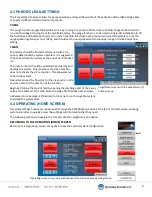
ATTENTION: Keep the system in
‘
Purge
’
mode until you see fluid dripping from the manifold.
9.
Once fluid has begun to drip from the manifold, the
‘
purge
’
function can be turned off.
10.
Select
‘
Recipes
’
from the navigation menu and configure the recipe to meet your spraying needs. Be sure to set
and be aware of the pump priming time, as this priming time will occur after the system has been triggered.


