NETWORKEDIO FIRMWARE CONFIGURATION AND SETUP V4.0
©2019 SPOTTERRF 06.18.2019 REV001
SpotterRF Technical Support | 801.742.5849 x4 | [email protected]
7
3D Rotating Radar System Calibration
Scope Referencing
The 3D Rotating Radar System will have a calibration scope within its case that is used in calibrating the radar within the
NIO map interface. Access the radar’s interface, navigate to the Advanced tab, and scroll down to Motor settings. Select
“Go to azimuth angle” and the radar head will stop spinning and rotate to the
azimuth angle
of the motor
. Attach the
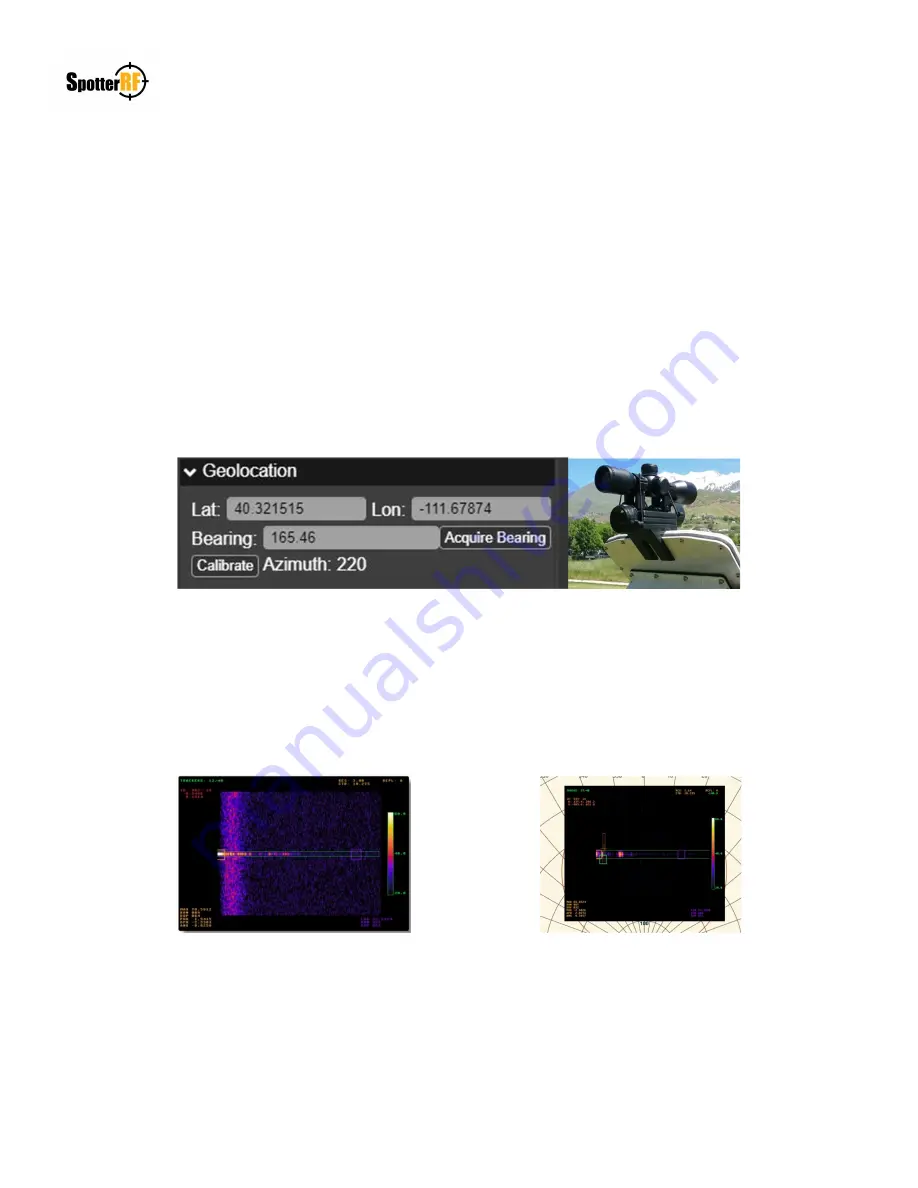
calibration scope to the radar as shown below. Scope should be centered over the radar face plate and screw. Do not
attempt to physically rotate the motor head. Use the Azimuth input field within Motor settings to adjust the radar’s
orientation to align the scope’s reticle at a reference point in the 360° field of view. Once the reticle is aligned, navigate to
the NIO interface and select the radar within the Devices icon. Select Geolocation, select Calibrate, click on the reference
point found on the map image in the NIO interface, then select Save. The Bearing line will have adjusted to that reference
point. Remove scope from radar. Navigate back to the Motor settings and select “Normal Operation Mode”.
Saturation Scan
Once calibrated, ensure there is minimal to no saturation within the radar’s 360° field of view. Select the “Saturation Scan
Mode” within the Motor settings and the rate of rotation will noticeably slow down. Navigate to the Tracker tab and select
“Show RDM”. This allows you to see how much saturation is present at the angle the radar is facing during its rotation.
Repositioning radar or radar fencing (SP-RDR-FENCE) may be needed to reduce saturation that is affecting performance
of drone detections.
RDM with Saturation
RMD without Saturation


