background image


NETWORKEDIO FIRMWARE CONFIGURATION AND SETUP V4.0 


©2019 SPOTTERRF 06.18.2019 REV001


SpotterRF Technical Support | 801.742.5849 x4 | [email protected] 


3D Rotating Radar System Configuration 


Radar (3D-500 / 3D-250) 

The 3D Rotating Radar’s interface functions the same as other SpotterRF radars, with exception of the following: 

1.


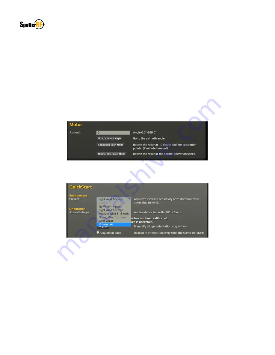
Motor controls are found on the Advanced tab of the radar interface. This allows the user to perform calibrations 
with the “Go to azimuth angle” button and to perform a Saturation Scan. The Saturation Scan will slow down the 
rotation rate of the motor for the user to view the Radar Doppler Matrix (RDM) found in the Tracker tab. Viewing 
the RDM during this mode allows the user to determine what angle is producing saturation/noise on the system, if 
present. 


2.


The Environment Presets have the option to select Rotating Air. This preset was made specifically for the rotating 
radar system in refining the sensitivity settings of drone detections. 


3.


Do not attempt to record target tracks with the rotating radar using the Manage Data Sources link. The Manage 
Data Sources link within the Advanced tab in the System section allows users to upload and play recorded tracks 
for filter applications on specific sites. This interface allows the user to record current tracks within the radar’s 
field of view. However, this recording feature is not functional within the rotating radar system due to processor 
limitations. 


Summary of Contents for 3D-250

Page 1: ...3D Rotating Radar System Setup Configuration and Calibration Supplemental Guide For reference to NIO version 4 0 4 and Spotter version 4 1 0...

Page 2: ...LE OF CONTENTS 3D Rotating Radar System Setup 3 Location 3 Physical Setup 3 Networking 4 3D Rotating Radar System Configuration 5 NetworkedIO HUB5 5 Radar 3D 500 3D 250 6 3D Rotating Radar System Cali...

Page 3: ...avoided Physical Setup The 3D Rotating Radar System will come in a Pelican Air case with all necessary equipment for setup and a Quickstart guide that is printed for reference Quickstart guides can a...

Page 4: ...5849 x4 support spotterrf com 4 3D Rotating Radar System Setup Networking The 3D Rotating Radar System has an accompanied Quickstart guide for use in Networking configuration and setup See example im...

Page 5: ...12 VDC port that can be activated and its use is for future SpotterRF devices or customized customer needs Be aware that new systems will have all port power defaulted to Off The NIO interface allows...

Page 6: ...trix RDM found in the Tracker tab Viewing the RDM during this mode allows the user to determine what angle is producing saturation noise on the system if present 2 The Environment Presets have the opt...

Page 7: ...align the scope s reticle at a reference point in the 360 field of view Once the reticle is aligned navigate to the NIO interface and select the radar within the Devices icon Select Geolocation select...

Page 8: ...D Rotating Radar System Calibration Radar Fencing The Radar Fencing Kit SP RDR FENCE is available for purchase separately from the 3D Rotating Radar System When the installation location and setup mus...

Page 9: ...de link at the bottom of the page Radar with then be upgraded to 3D system capabilities Software Configurations The current limitation of the 2D Rotating Radar System is the inability to measure the a...

Reviews: