NETWORKEDIO FIRMWARE CONFIGURATION AND SETUP V4.0
©2019 SPOTTERRF 06.18.2019 REV001
SpotterRF Technical Support | 801.742.5849 x4 | [email protected]
5
3D Rotating Radar System Configuration
NetworkedIO (HUB5)
The 3D Rotating Radar System comes with the HUB5 NetworkedIO device. The HUB5 has ability to enable/disable
passive PoE connections within the following ports: PoE RADIO/LAN, PoE RADAR 1/LAN, and PoE RADAR 2/LAN.
These ports are still able to maintain data connection even when PoE is disabled. The ACTIVE PoE CAMERA port also
can be toggled on and off from the NIO’s interface, but data connection is not enabled while power is off on the port. The
PASSTHROUGH 24 – 48 VDC port is activated within the NIO’s interface and is needed to supply power to the rotating
motor on the system. There is also a DC OUT 12 VDC port that can be activated and its use is for future SpotterRF
devices or customized customer needs.
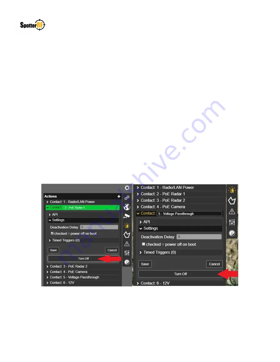
Be aware that new systems will have all port power defaulted to Off. The NIO interface allows the user to deselect this
power option (See any picture below). Toggling the Turn ON / Turn Off interface button will display a green action alert
and this occurrence will be dependent on the “power off on boot” state selected in defining default operation of port
power (See example pictures below). The reason PoE Radar 1 action is lit green is because its expected state is to be
powered off (box is checked) and its current state is turned on. The reason the Voltage Passthrough action is not lit green
is because its expected state is to be powered on (box is unchecked) and its current state is turned on. Selected the “Turn
Off” button in both pictures below would change their current states and action commands to either turn off the green
highlight (e.g. PoE Radar 1) or turn on the green highlight (e.g. Passthrough).