background image

6

• 

Pour éviter de vous blesser, restez sur les bandes de repos (barres latérales) 

avant de démarrer le tapis de course. 

• 

Ce tapis de course n’est pas destiné à être utilisé par des personnes (y com-

pris des enfants) dont les capacités physiques, sensorielles ou mentales sont 

réduites ou qui ne disposent pas de l’expérience ou du savoir nécessaires, sauf 

si celles-ci ont au préalable été formées eu égard à l’utilisation de ce tapis de 

course par une personne responsable de leur sécurité.

•  Les enfants doivent être encadrés afin d’empêcher qu’ils ne jouent avec le 

tapis de course.

• 

Utilisez toujours le clip de sûreté pendant le fonctionnement du tapis de 

course.

• 

NE PAS rester sur le tapis de marche lors du démarrage du tapis de course. 

Enjambez le tapis et placez vos pieds sur les bandes de repos droite et gauche.

• 

Pour éviter de vous blesser, restez sur les bandes de repos (barres latérales) 

avant de démarrer le tapis de course.

ATTENTION

Si vous ressentez une douleur ou si vous avez une sensation anormale, AR-
RÊTEZ VOTRE ENTRAÎNEMENT et consultez immédiatement votre médecin.  
Entraînez-vous à votre niveau d’exercice recommandé. NE PAS s’entraîner jusqu’à 
l’épuisement.

• 

Avant de commencer un programme d’exercice, vous devriez consulter votre 

médecin. Il est recommandé de faire un examen physique complet.

• 

NE PAS monter sur l’étape plus haute. En maintenant sur les supports de 

stabilité, monter sur l’ étape plus bas. 

• 

Pour diminuer le risque de choc électrique, débranchez toujours ce tapis de 

course de la prise de courant, immédiatement après utilisation et avant le nettoy-

age.

• 

Un branchement incorrect du connecteur de mise à la terre de l'équipement 

risque d'entraîner un choc électrique. En cas de doute sur la mise à la terre cor-

recte de l’elliptique, faites appel à un technicien ou un électricien qualifié. NE 

PAS modifier la fiche fournie avec l’elliptique, si elle ne correspond pas à la prise, 

faites installer une prise adéquate par un technicien qualifié.

Remarque: Ce matériel a été testé et déclaré conforme aux normes des appareils 
digitaux de Classe B, conformément à la partie 15 du Règlement de la FCC. Ces 
limites sont conçues pour offrir une protection raisonnable contre les interférences 
nuisibles dans une installation résidentielle. Cet appareil génère, utilise, et peut dif-
fuser des signaux radioélectriques, et, s’il n’est pas installé et utilisé conformément 
aux instructions, peut provoquer des interférences nuisibles aux communications 
radio. Cependant, il n’y a aucune garantie que des interférences ne se produiront 
pas dans une installation particulière. Si l'utilisateur désire corriger les interférenc-
es, ces corrections seront à la charge de l’utilisateur 

Dans ce manuel, les mots “gauche” et “droit” sont utilisés en référence aux pièces 
et au produit. Comme tels, les mots “gauche” et “droit” font respectivement ré-
férence aux côtés gauche et droit de l’exerciseur. De même pour plus de conci-
sion, le mot «vis» est utilisé dans certains cas où des rondelles, des vis et autres 
matériels sont associés. 

2. CONSIGNES DE SÉCURITÉ (SUITE)

Summary of Contents for T645L

Page 1: ...T645 LED Treadmill Owner s Manual...

Page 2: ...DISPLAY Safety Key 28 6 OPERATE THE PRODUCT 28 OPERATION Quick Start 28 OPERATION Start a Workout Program 29 OPERATION Display 30 OPERATION Cool Down 30 OPERATION Idle Mode 30 OPERATION Energy Smart F...

Page 3: ...designed for years of reliable performance this product was made for full commercial use Before this product is assembled or operated we recommend that you familiarize yourself with this manual Unders...

Page 4: ...rking properly or has been dropped or damaged contact a service technician for repairs Do not use accessories that are not specifically recommended by the manufacturer Such parts might cause injuries...

Page 5: ...xpense WARNING Only qualified technicians should be allowed to contact electrical components such as circuit boards Some components carry an electrical charge even after use has been discontinued or t...

Page 6: ...iquement pour l usage pr vu dans ce manuel N utilisez jamais ce tapis de course s il a t endommag de quelque fa on que ce soit S il ne fonctionne pas correctement ou s il est tomb ou endom mag contact...

Page 7: ...minuer le risque de choc lectrique d branchez toujours ce tapis de course de la prise de courant imm diatement apr s utilisation et avant le nettoy age Un branchement incorrect du connecteur de mise l...

Page 8: ...No Name Qty A1 Display 1 A6a Motor right cover 1 A2 Handlebar assembly 1 A6b Motor left cover 1 A3 Right pedestal 1 A7 Left pedestal 1 A4 Feeder cord 1 A8 Owner s manual 1 A5 Waterproof ring 2 A9 Har...

Page 9: ...shaped Allen wrench 1 M6 T shaped Allen wrench 1 M6 Double open end wrench 1 22 24 Screwdriver handle 1 green Screwdriver shank 1 Phillips and flat Components on the Product No Name Specification Note...

Page 10: ...used where screws washers and other hardware may be involved And for clarity names of keys are capitalized STEP 0 Preparation Separate product from the Package Follow the A B C sequence and lay the ma...

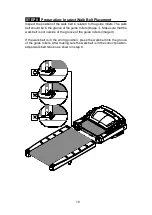
Page 11: ...ould be in the groove of the guide rollers image Make sure that the walk belt is not outside of the groove of the guide rollers image X If the walk belt is in the wrong position press the walk belt in...

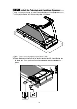
Page 12: ...l the pedestals and handlebar assembly The illustration below provides an overview of this step a First remove screws 41 from pedestal mounts b Next inspect the spring clip A and screw socket B to see...

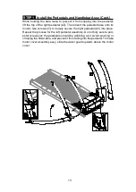
Page 13: ...n Note make sure the cable is fully pull out of the oval opening from the pedestal mount b Place the right pedestal A3 on the floor as shown with the bottom end facing the data cable Detach the feeder...

Page 14: ...al base onto its mount Use screws 41 to loosely secure the right pedestal A3 into place Repeat the process for the left pedestal assembly Do not fully secure ped estal screws yet the pedestals should...

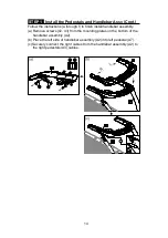
Page 15: ...finish install handlebar assembly a Remove screws 42 43 from the mounting plates on the bottom of the handlebar assembly A2 b Place the left side of handlebar assembly A2 into left pedestal A7 c Secu...

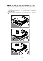
Page 16: ...A2 into right pedestal A3 Make sure the cable is not shown or pinched e Put the previously removed screws 42 43 back into the pedestals Tighten the screws 42 at the B area first then tighten the screw...

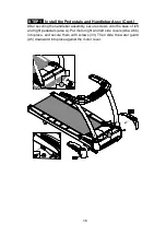
Page 17: ...er securing the handlebar assembly secure screws onto the base of left and right pedestals area A Put motor right and left side covers A6a A6b into place and secure them with screws 33 Then slide the...

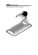
Page 18: ...17 STEP 2 Install the Display Follow instructions below to install the display onto the cowling The illustration below provides an overview of this step...

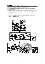
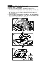
Page 19: ...the handlebar assembly A2 b Place the display A1 onto the handlebar assembly A2 Note make sure the display is aligning with its guiding pieces to avoid damaging the control board c Push the display A1...

Page 20: ...ligning it correctly then press it into place on the handlebar assembly Note make sure the cables are not pinched Also make sure the display is resting outside of the handlebar assembly f Hold the dis...

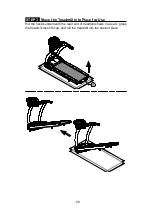
Page 21: ...20 STEP 3 Move the Treadmill into Place for Use Put the hands underneath the read end of treadmill shown in area A grasp the treadmill then lift it up and roll the treadmill into the desired place A...

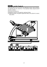
Page 22: ...nspect whether the treadmill rests flat on the floor If the treadmill wobbles adjust treadmill levelers as follows a Loosen the leveler nut b Rotate the leveler foot downward touching the floor c Rota...

Page 23: ...salignment c Adjust the speed higher to 15kph 10mph or above to ensure the belt is aligned d Adjust the rear roller screw if necessary to make sure the belt fall in the middle of 2 green labels in the...

Page 24: ...30 mm about 1 1 8th inch A hanging gauge should measure the weight at 3 kg or 6 6 lb Adjust the tension if it differs from this specification If the walk belt is too loose use a hex wrench to turn rea...

Page 25: ...irst remove screws 45 from the power cord socket on the product Insert the power cord into place on the product Secure the power cord A10 connector screws 45 And insert the other end of the power cord...

Page 26: ...from this product 1 Pulse LED 11 Pause Resume Key 2 Weight Loss Target Heart Rate 12 Quick Start Key 3 Actual Heart Rate 13 Wake Up Key 4 Cardio Target Heart Rate 14 Change Display Key 5 Dot Matrix Di...

Page 27: ...ogram illustrations DISPLAY Keys Display key functions are introduced briefly below QUICK START Press this key to start exercising without first entering age weight and other user information PAUSE RE...

Page 28: ...y to lock current heart rate as the target heart rate to train on FIT TEST FIT TEST offers eight types of fitness tests Bruce Gerkin WFI Army Marines Navy Air Force and PEB 0 9 numeric keys Press thes...

Page 29: ...r If the safety key is removed and then put into place while the walk belt is rotating the workout will resume as follows Time distance and caloric expenditure values will remain lit PRESS SPEED UP wi...

Page 30: ...ometers If the program time limit is activated at the user preference setting then the DISTANCE goal will be deactivated Use keys or numeric keys 0 9 to adjust the setting Press the ENTER key to confi...

Page 31: ...istance or calorie expenditure has been ob tained the product will enter a two minute cool down period The display will count down from two to zero When the countdown reaches zero the cool down period...

Page 32: ...L There are three hill workouts HILL 1 HILL 2 and HILL 3 each of which is represented by a different hill illustration One of the three hill illustrations will appear each time the hill key is pressed...

Page 33: ...function is activated the time limit will become the workout goal FAT BURN In this program there are 1 20 different difficulty levels to select from During program setting before entering program mod...

Page 34: ...hes 180 cm a HEIGHT xxx INCH or HEIGHT xxx CM will appear b Press the SPEED key the INCLINE key or press numerical keys 0 9 to select your height c Press the ENTER key to confirm your choice d During...

Page 35: ...n the fitness test begins the message screen will show y y MILES xx xx where y y represents the distance goal and xx xx represents the time goal If the exerciser finishes the test before the allotted...

Page 36: ...hen the test begins the message window will show y y MILES xx xx where y y represents the distance goal and xx xx represents the time goal When the test comes to completion or when someone presses the...

Page 37: ...eed to maintain at this target If the actual heart rate falls outside of 84 200bpm then this program can t be activated and the message will display HR RANGE IS 84 200 3 HRC Heart Rate Control mode Th...

Page 38: ...ntrol workout is activated a heart illustration will appear on the dot matrix screen When the actual heart rate signal is detected the color of the heart illustration will alternate between red and gr...

Page 39: ...timer of 30 minutes When a timer is set the console will shut power off when the timer is reached during idle mode To set timer the message display will show ZZZ TIMER xx MIN press keys to change the...

Page 40: ...otor overload abnormality Restart the unit to recover normal functions ERROR_2_1_ IGBT excessive current Restart the unit to recover normal functions ERROR_2_2_ IGBT excessive heat The treadmill will...

Page 41: ...er contact Because the telemetry heart rate signal varies in strength from 20 Hz to 20 KHz environmental interference can block signal reception Physical vibration and electronic devices including ste...

Page 42: ...ate goal would be appropriate for you HOW LONG SHOULD I EXERCISE The duration of your workout must depend on your fitness level In general it is recommended that you maintain a heart rate within your...

Page 43: ...ell as ECOFIT System and MYE Wireless TV Audio_Channel Re ceivers iPod iPhone iPad 30 pin connector Option When connecting the device to the 30pin connector user can listen to music via headphone jack...

Page 44: ...member cards Not available yet b Bluetooth WIFI connection button press this button to pair the smart phone SA WELL App c USB port this port is used for device charging as well as optional data trans...

Page 45: ...Audio_Channel Receivers the display must has Channel Keys Please make sure your equipment is with the correct sticker as below b Treadmill Left display Without Channel Keys Right display With Channel...

Page 46: ...ess TV frequency in Europe is 863MHZ 800MHZ 2 Installation instruction Turn off the power and plug the receiver into the CSAFE port RJ45 in the left of display and then turn on the power 3 VOLUME keys...

Page 47: ...Replace a Fuse If electrical current becomes too high the fuse breaks This protects the product To replace a fuse follow instructions a through g below a Press the fuse cap inward using a tool b Turn...

Page 48: ...nt Bottle Auto Lubricate 40 Times 1000km time Lubricant Change Procedure Note Pay extra attention during the lubricant changing procedure to avoid electric shock especially operating it while the powe...

Page 49: ...e nicely Pay attention to the lubricant hose direction when place the bottle into the system Also note the following 1 Even if the Lubricant bottle exchange warning is not displaying it is still OK to...

Page 50: ...buzzer will sound for 30 seconds The buzzer will sound for 2 sec onds and stop for 2 seconds The buzzer will stop working after 30 seconds Replace lubrica tion VR motor ERR 02 EEPROM damaged If an abn...

Page 51: ...properly 4 Walk belt Inspect alignment centering and look for wear 5 Walk deck Inspect for wear 6 Belt guides Inspect for normal rotation 7 Rear roller Inspect for normal rotation 8 Front roller Insp...

Page 52: ...the rear roller for normal rotation 5 Remove dust and debris from the motor compartment Yearly 1 Replace the drive belt once every three years 2 Replace the lubricant bottle every 40 000km 25 000mile...

Page 53: ...ter 2 Quarter 3 Quarter 4 Completed Yearly Tasks Year 1 Completed Notes __________________________________________________________ ________________________________________________________________ ____...

Page 54: ...pter Board CSAFE Board Numeric Key Board Control Board HTR Board HRC Board Contact HTR plates Fan Fan Board Safety Key Board Bridge Board Speed Incline Keypad Board Incline Sensor Incline Control Moto...

Reviews: