background image

INTRODUCTION

Congratulations on purchasing one of the finest pieces of exercise equipment on the
market today. Constructed of high quality materials and designed for years of
trouble-free usage, the elliptical will be an integral part of your health and fitness.

Before using your elliptical trainer, we recommend that you familiarize yourself with
the owner's manual. Whether you are a first time user of an elliptical trainer or a
seasoned "pro", understanding the correct use of the equipment will enhance your
ability to achieve your exercise goals safely and successfully.

LEFT SUPPORT TUBE

ROCKING BAR

PIVOT ENCLOSURE

ADJUST LINKAGE

ROCKING BAR COVER

FLOOR LEVEL ADJUSTMENT

GLIDE RAIL

POWER SWITCH

TRANSPORST WHEEL

REAR COVER

FOOT PEDAL

RIGHT SUPPORT TUBE

WATER BOTTLE HOLDER

STATIONARY HANDLE BAR

STRIDE SWITCH

ELECTRONICS DISPLAY

LEVEL SWITCH

UPPER BODY HANDLE BAR

PDF created with pdfFactory trial version 

www.pdffactory.com

Summary of Contents for 805p

Page 1: ...PDF created with FinePrint pdfFactory Pro trial version http www pdffactory com ...

Page 2: ...L SET STRIDE ADJUSTMENT PROGRAM USING THE INTERVAL MODE RESET KEY FUNCTIONS DEFINITIONS HEART RATE CONTROL FEATURE if applicable E GUILDLINES FOR EXERCISE HOW LONG SHOULD I EXERCISE HOW OFTEN SHOULD I EXERCISE F MAINTAINING YOUR ELLIPTICAL TRAINER CLEANING YOUR ELLIPTICAL TRAINER G TROUBLE SHOOTING H WIRING SCHEMATIC 1 2 3 3 4 11 12 12 12 13 13 15 16 16 17 19 19 19 19 21 23 PDF created with pdfFac...

Page 3: ...n t rock the unit from side to side and take care when mounting and dismounting the unit Only stand on provided foot pedals Allow sufficient space on both sides of the elliptical for users to mount and dismount the machine Do not use any accessories that aren t specifically recommended by the manufacturer as these might cause injuries or cause the unit to fail If any parts fail or are defective pl...

Page 4: ...al Whether you are a first time user of an elliptical trainer or a seasoned pro understanding the correct use of the equipment will enhance your ability to achieve your exercise goals safely and successfully LEFT SUPPORT TUBE ROCKING BAR PIVOT ENCLOSURE ADJUST LINKAGE ROCKING BAR COVER FLOOR LEVEL ADJUSTMENT GLIDE RAIL POWER SWITCH TRANSPORST WHEEL REAR COVER FOOT PEDAL RIGHT SUPPORT TUBE WATER BO...

Page 5: ...ed dealer 1 Four 3 8 x L1 bolts lift post and frame 2 Four 3 8 washers lift post and frame 3 Two 3 8 x L3 4 bolts lift post and frame 4 Two 5 16 x L1 3 4 bolts moving bar and linkage 5 Two 5 16 washers linkage 6 Four 5 16 x L19 bolts support tube 7 Four 5 16 washers support tube 8 Two 1 4 x L3 4 screws rocking bar 9 Two 1 4 washers rocking bar 10 Eight M5 x L12 PH screws foot pedals 11 One M5 x L1...

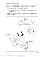
Page 6: ...uctions before you begin 1 Remove only the upper box and Styrofoam see Fig 1 Do not remove the lower box and Styrofoam until you finished assembly step 5 see Fig 4 2 Raise the main post into upright position and secure it with 3 8 bolts by wrench provided see Fig 1 Note Styrofoam Styrofoam Box Fig 1 PDF created with pdfFactory trial version www pdffactory com ...

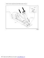
Page 7: ...3 Remove the lower roller and shaft as shown in Fig 2 Fig 2 PDF created with pdfFactory trial version www pdffactory com ...

Page 8: ...4 Place the glide rail over the rocking bar roller see Fig 3 Fig 3 Styrofoam Styrofoam Box PDF created with pdfFactory trial version www pdffactory com ...

Page 9: ...ar and secure with screw as shown in diagram A then cover with the end cap Following that remove all the Styrofoam and packing box see Fig 4 Remove all the Styrofoam and packing box Fig 4 Styrofoam Styrofoam Box PDF created with pdfFactory trial version www pdffactory com ...

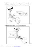
Page 10: ...n fasten the foot pedals with screws Secure the lower roller with the shaft and fasten the shaft by open end wrench see Fig 5 7 Tighten the pivot enclosure with the screw provided see Fig 6 Fig 5 Fig 6 PDF created with pdfFactory trial version www pdffactory com ...

Page 11: ...e support tubes with the 1 4 x L 3 4 bolts to the upper tube mount and secure them tightly Use T handle wrench to secure 5 16 x L 3 4 bolts on the lower tube mount Then cover with water against cap See Fig 8 Fig 7 Fig 8 PDF created with pdfFactory trial version www pdffactory com ...

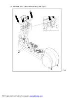
Page 12: ...10 Screw the water bottle holder securely See Fig 9 Fig 9 PDF created with pdfFactory trial version www pdffactory com ...

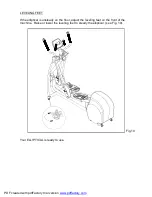
Page 13: ...teady on the floor adjust the leveling feet on the front of the machine Raise or lower the leveling feet to steady the elliptical see Fig 10 Your ELLIPTICAL is ready to use Fig 10 PDF created with pdfFactory trial version www pdffactory com ...

Page 14: ...n to MAN L 3 If you stop anytime during your workout you will be prompted by STEP to continue your workout then the display will automatically return to MAN L All input data TIME STEPS CAL etc will be retained 4 You can use the MODE key to switch between SCAN TIME STEPS CAL or PULSE 5 Use the MODE keys to set your desired TIME or STEPS then press ENTER to input this data 6 When you reach your desi...

Page 15: ...y SPM STRIDES MIN The elliptical trainer offers three 3 professionally designed workout programs from which to choose The program controls the tension level automatically throughout your workout 1 Press the PROGRAM key to scroll between the three 3 Programs and the PROG X X means 1 2 or 3 will appear When you have selected the program you want press ENTER to confirm If you don t press ENTER the di...

Page 16: ...rammed levels you can change the level anytime during your workout If you stop in the middle of your workout you will be prompted by STEP to continue your workout All input data TIME STRIDE LENGTH LEVEL STEPS CAL etc will be retained PDF created with pdfFactory trial version www pdffactory com ...

Page 17: ...you press ENTER SEG 2 will appear in the window Repeat the steps above for Segments 2 8 If you don t want to set all 8 segments you can set the TIME for the final segment to zero For example if you only want to set four segments leave segment 5 s TIME with a value of zero and the Elliptical 805P will use only the first four segments S1 S2 S3 S4 BLANK 4 Once you have set all desired segments press ...

Page 18: ...n your desired time is reached If your workout continues the unit will start to count up STEPS Use the keys to set your desired steps Each press of the key changes the steps in increments of 5 steps Pressing and holding the key will change the display by 50 steps every 0 5 seconds When you have reached your desired steps press ENTER During your workout the electronics package will count down and t...

Page 19: ...PDF created with pdfFactory trial version www pdffactory com ...

Page 20: ...sly selected and start to count down The computer will automatically adjust the resistance Level according to the Heart Rate of the user 7 When the Time is reached the HEART RATE CONTROL program will be completed The resistance Level will decrease to Level 5 as COOL DOWN then the program will default to MANUAL mode If the Level is equal or less than Level 5 when the target Time is reached the comp...

Page 21: ...ance The elliptical trainer s low friction operation is dependent on keeping the unit as clean as possible See Cleaning the elliptical trainer for more information Regular cleaning is recommended to keep your elliptical trainer at peak performance Before your workout use a dry cloth to clean the surface of the electronics display Note Never pour liquids on the electronics display Should water for ...

Page 22: ...p see fig 12 b Refill with the lubrication tube and the lubrication valve see fig 12 1 c Then remove the lubrication tube see fig 12 2 d Replace the access cap see fig 12 3 Fig 11 Fig 11 1 Fig 11 2 Fig 12 Fig 12 1 Fig 12 2 Fig 12 3 Fig 11 3 step step Lubrication valve PDF created with pdfFactory trial version www pdffactory com ...

Page 23: ...ing the fuse Find the 1A fuse 100 120V 1A fuse 200 220V holder on the front of the machine then push on the fuse holder and turn it counterclockwise to remove the damaged fuse see Fig 13 1 13 2 Insert a new fuse into the holder push the fuse and holder into place then turn the fuse holder clockwise to secure it Fig 13 3 13 4 A Blank display CAUTION To remove To install Fig 13 1 Fig 13 3 Fig 13 2 F...

Page 24: ...n the display returns to normal OR you press the STRIDE keys to adjust the stride length and ERR 7 appears and blinks please contact your dealer for further information because the stride system is damaged and should not be used If there is no load or the load does not respond properly when you press the LEVEL keys please contact your dealer for further details If your display has no SPM reading d...

Page 25: ...Wiring Schematic 805P Your Authorized Distributor PDF created with pdfFactory trial version www pdffactory com ...

Reviews: