7
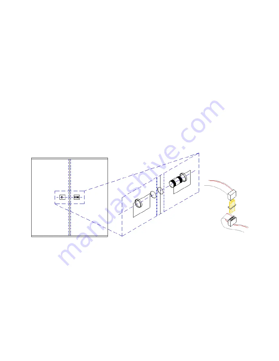
1 Remove the screws securing the access doors, if previously installed, on the left side of section
A and the right side of section B, if viewing the scoreboard from the rear. (For access door
locations, see illustration below.)
2 Place one of the supplied bushings in the hole between the two scoreboard sections, and
tighten one of the supplied ring nuts onto each end of the bushing. (See Figure 5-1 below)
Repeat the installation for each remaining section.
3 Once the crossover bushings are installed, all wiring harness connections should be made
between cabinets before the access doors are replaced. Inside each set of access doors
connect all wiring harnesses between cabinets. For each set of harness connections between
scoreboard sections there will be one (1) ribbon cable connection and multiple power
connections. When making the ribbon cable connections between cabinets, ensure that the
RED STRIPES LINE UP
with one another when the cables are connected. (See Figure 5-2
below) When making the power connections, each female power connector should mate with
one male power connector in the other section.
PLEASE NOTE:
It makes no difference which
female connector mates with what male connector.
4 Replace all access doors.
MOUNTING THE SCOREBOARD


