


SPONGE-JET 35E 50E USER MANUAL |
7
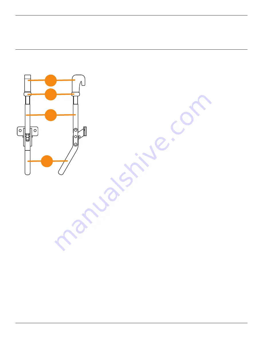
BASIC COMPONENTS
(CONTINUED)
Figure C:
Pan Clamps
1
Pan Clamp Hook
Adjustment for varying sized gaskets is made by turning Pan Clamp Hook.
2
Lock Nut
Used to prevent Pan Clamp Hook from swiveling when dismounting Pan Clamps
(50E only)
.
3
Threaded Rod
Pan Clamp Hook threads onto Threaded Rod.
4
Handle
Used to secure Pan Clamp to Sieve Assembly.
1
2
3
4


