Machine Guard MG4-REF11 A
21
SPM Instrument AB
• Box 504 • SE-645 25 Strängnäs • Sweden
Technical data are subject to change without notice.
Tel +46 152 225 00 • Fax +46 152 15075 • [email protected] • www.spminstrument.com
ISO 9001:2000 certified © SPM 2017-09. 71947 B
Installation of shock pulse transducers
A transducer installation is useless if signal strength is lost through incorrect installation. The
transducer’s conical seat surface must have firm contact with the material of the bearing housing.
Drill and thread to the required depth, and torque correctly. Try to point the transducer straight
at the bearing.
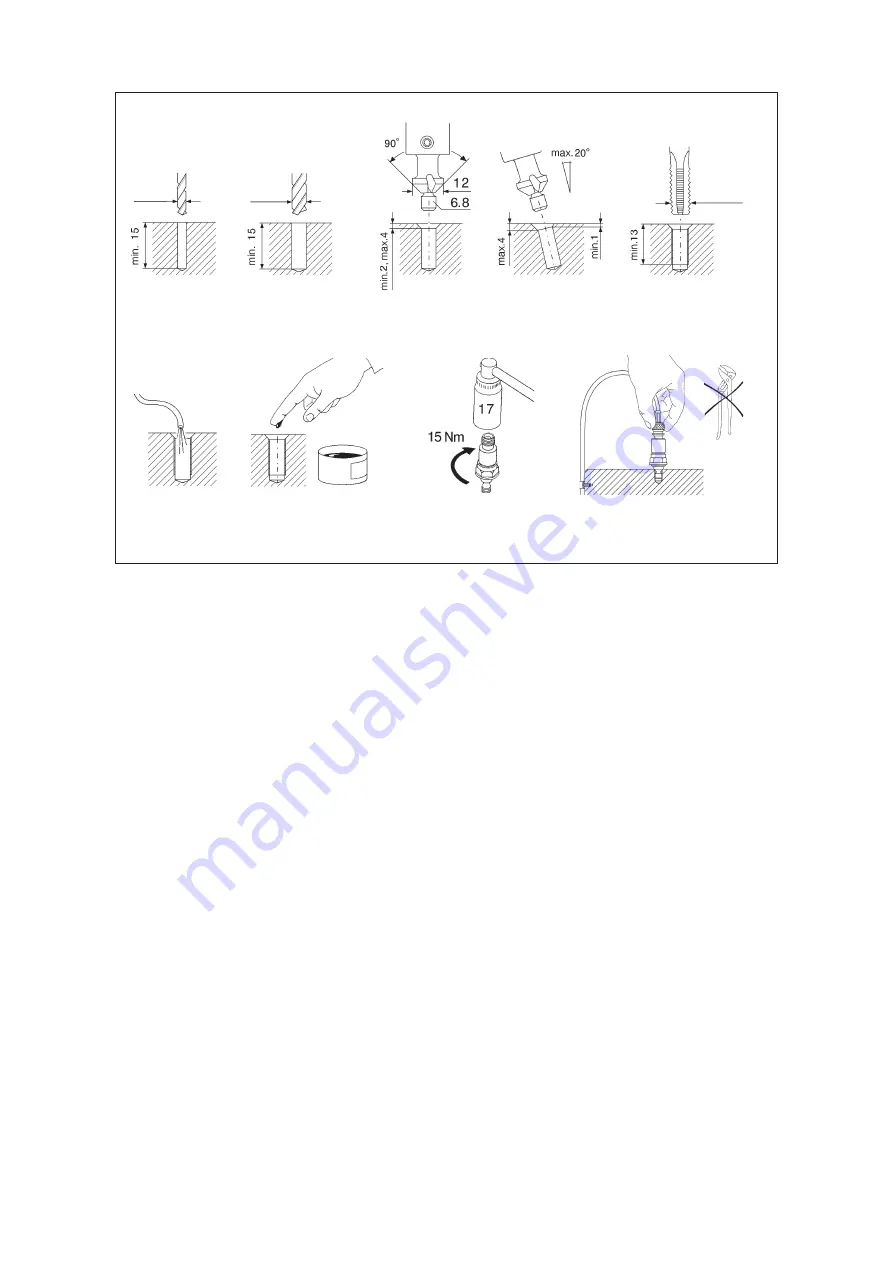
The installation is made as follows:
1
Drill a pilot hole with a 3.0 mm drill bit, depth 15 mm. With a 15 mm hole, you will stay within
tolerances if you countersink and thread as deep as the tools will go.
2
Enlarge the hole with a 6.9 mm bit for M8 (6.6 mm bit for UNC 5/16”). This recommended
drill bit is 0.1 mm above standard size, to prevent the pilot from jamming and breaking.
3
Countersink the hole, using a 90° countersink with pilot 6.8 (6.5) mm. Countersinking depth
is min. 2 mm ,max. 4 mm (min. 1 mm at the shallowest point when the transducer is mounted
at an angle to the surface of the bearing housing).
4
Thread the hole for M8 (UNC 5/16”), to a depth of min. 13 mm.
5
Blow the chips out of the hole, using compressed air or a small tube. Chips left in the mount-
ing hole can knock against the transducer when the machine vibrates and produce an inter-
fering shock signal. The hole must be clean.
6
Put some clean grease on the seat surfaces to improve signal transmission. Loctite or a simi-
lar adhesive may be used to secure the transducer on vibrating machines.
7
Torque the transducer with a torque wrench. The torque is 15 Nm (11 lbf./ft.).
8
Make sure that the seat surface has firm connection with the material of the bearing housing.
Connect the transducer cable by hand. Do not use pliers on a standard TNC connector.
1
2
6
7
3
5
8
4
3.0
(3.0)
6.9
(6.6)
(6.5)
M8
(UNC 5/16”)
Summary of Contents for Machine Guard MG4-REF11A
Page 2: ......


