61
m)
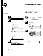
Vuelvan a montar el dispositivo de mezclado superior
(O) de manera que su corona dentada esté alineada
con la inferior para que el perno delantero encaje
perfectamente en su alojamiento que se encuentra en
el depósito (véase fig. 22).
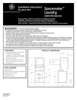
n)
Desmonten el recipiente recoge-gotas (AA) girándolo
ligeramente hacia arriba y tirando de él hacia el
exterior (véase fig. 23). Laven concienzudamente
cada parte y vuelvan a montarlas siguiendo las
operaciones anteriormente mencionadas en sentido
inverso observando la precaución de introducir el tubo
de descarga del líquido de condensación (AB) en su
propio alojamiento.
Fig. 23
Fig. 22
Fig. 21
Summary of Contents for FROSTY DREAM 2
Page 2: ......
Page 63: ...63 ESPLOSO FROSTY DREAM 2 EXPLODED VIEW FROSTY DREAM 2 ...
Page 64: ...64 SCHEMA ELETTRICO FROSTY DREAM 2 WIRING DIAGRAM FROSTY DREAM 2 ...
Page 65: ...65 ESPLOSO FROSTY DREAM 3 EXPLODED VIEW FROSTY DREAM 3 ...
Page 66: ...66 SCHEMA ELETTRICO FROSTY DREAM 3 WIRING DIAGRAM FROSTY DREAM 3 ...
Page 69: ...69 NOTES ...
Page 70: ...70 NOTES ...